Housing-spindle sub-assembly, Dw2b integral brake check – JLG 450A_AJ Series II Service Manual User Manual
Page 66
SECTION 3 - CHASSIS & TURNTABLE
3-16
– JLG Lift –
3121180
Housing-Spindle Sub-Assembly
NOTE: Spray a light film of oil on all component parts during
assembly.
UNCONTROLLED OBJECTS CAN CAUSE EYE DAMAGE OR SERI-
OUS INJURY. ALWAYS WEAR EYE PROTECTION.
1. Press Bearing Cup (1C), position A, into Housing
(1E) using appropriate pressing tool (See back of
manual).
DO NOT USE EXCESSIVELY HIGH PRESSURE TO PRESS IN
STUDS OR HOUSING MAY CRACK. MAKE SURE HEAD OF STUD
CONTACTS FACE OF FLANGE ON HOUSING.
2. Turn Housing (1E) over and place into pressing
base. Press nine Studs (1H) into Housing (1E).
NOTE: Spray a generous amount of oil on bearings during
installation.
3. Press Bearing Cup (1C), position “B”, into Housing
(1E) using “B” Bearing Cone pressing tool (see back
of manual).
4. Place Bearing Cone (1D), into Bearing Cup (1C),
position “B”.
5. Grease Seal (1B) lip and press seal into Housing
(1E) using seal pressing tool (see back of manual)
until seal is flush with end of Housing.
6. Turn Housing (1E) over and lower onto Spindle (1A).
7. Install Bearing Cone (1D) into Bearing Cup (1C),
position “A”. and lightly press on Bearing Cup using
the “A” Bearing Cone pressing tool (see back of
manual) while rotating Housing (1E) in both direc-
tions to seat bearings.
8. Place Bearing Spacer (1F) on top of Bearing Cone (1D).
9. Using retaining ring pliers, install Retaining Ring
(1G) into Spindle (1A) groove. Make sure ring is
completely seated in groove.
NOTE: Extra bearing pre-load caused by pressing “A” Bear-
ing Cone (1D) must be removed. This should be
done by placing a flat piece of steel or a pressing
tool on the end of the spindle, and then lightly strik-
ing the tool with a piece of barstock. This should be
adequate to remove any additional bearing pre-load.
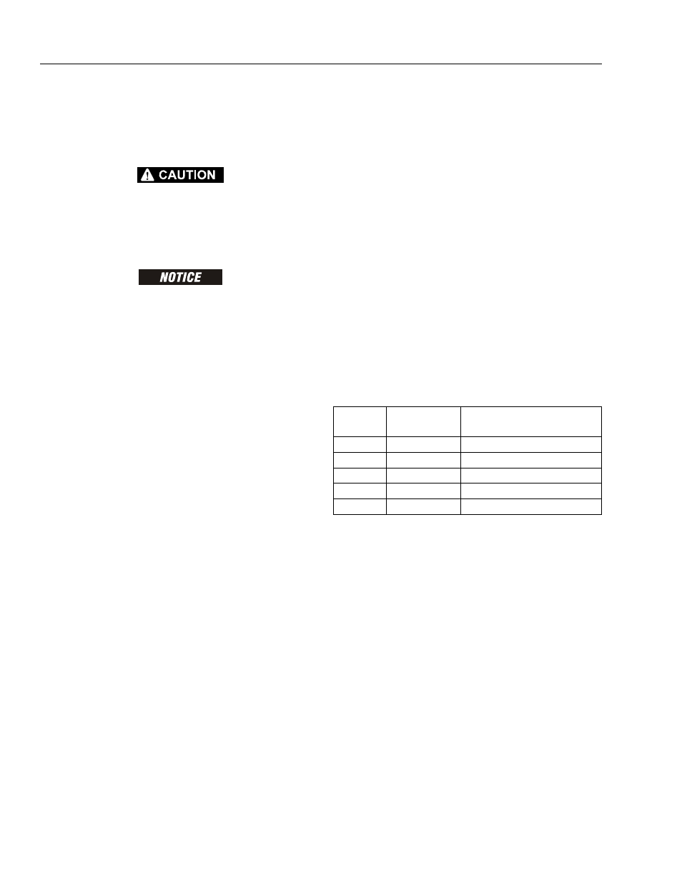
DW2B INTEGRAL BRAKE CHECK
1. Connect hydraulic line from hand pump to brake
port.
2. Check brake is set by trying to rotate Input Shaft (7).
This can be accomplished by installing an appropri-
ate tool (any tool that can locate on splines of the
Input Coupling (9), such as a mating splined shaft)
into Input Coupling (9)
3. Bleed brake. Increase hydraulic pressure gradually
while trying to rotate input until brake just starts to
release. Note this pressure. Make sure pressure falls
into appropriate range below:
4. Increase pressure to 3,000 psi and hold for 30 sec-
onds to check for leaks. Repair leaks if necessary.
NOTE: Make sure brake re-engages when pressure is
released.
NOTE: When done, make sure Input Coupling (9) is cen-
tered in Spindle (1A) to make installation of motor
possible without release of brake.
BRAKE
CODE
BRAKE P/N
JUST RELEASE
PRESSURE RANGE (psi)
A
902337
185-230
B
902341
155-192
C
902342
125-155
D
902343
93-115
E
902345
132-172