Shaft seal and shaft replacement, Shaft seal and shaft replacement -36, Shaft seal components -36 – JLG 450A_AJ Series II Service Manual User Manual
Page 326: Installation of shaft seal -36
SECTION 5 - HYDRAULICS
5-36
– JLG Lift –
3121180
5. Install new O-ring on valve plug. Reinstall poppet,
spring, and plug (with shims and O-ring) into pump
housing. Torque to 40-100 ft-lb (55-135 Nm).
SCREW ADJUSTABLE STYLE
1. Mark plug, lock nut, and housing to maintain original
adjustment before removing screw adjustable relief
valve plug. Loosen lock nut (1-1/16" Hex) and remove
plug (8 mm Int. Hex). Remove O-ring from plug.
2. Remove spring and poppet from housing.
3. Inspect poppet and mating seat in housing for dam-
age or foreign material.
4. Install new O-ring on valve plug. Reinstall poppet and
spring. Reinstall plug and lock nut. Torque to 34 - 42
ft-lb (47-57 Nm), aligning marks made at disassembly.
5. Check and adjust, if necessary, charge pressure.
For screw adjustable “anti-stall” charge relief valves,
an approximate rule of thumb is 2.8 bar/quarter turn
(40 psi/quarter turn).
6. Measure charge pressure (port M3) with pump in
stroke. Charge pressure should level off when relief
setting is reached.
Shaft Seal and Shaft Replacement
A lip type shaft seal is used in Series 42 pumps. Seal and
shaft can be replaced without major unit disassembly.
Replacement generally requires removing pump from
machine.
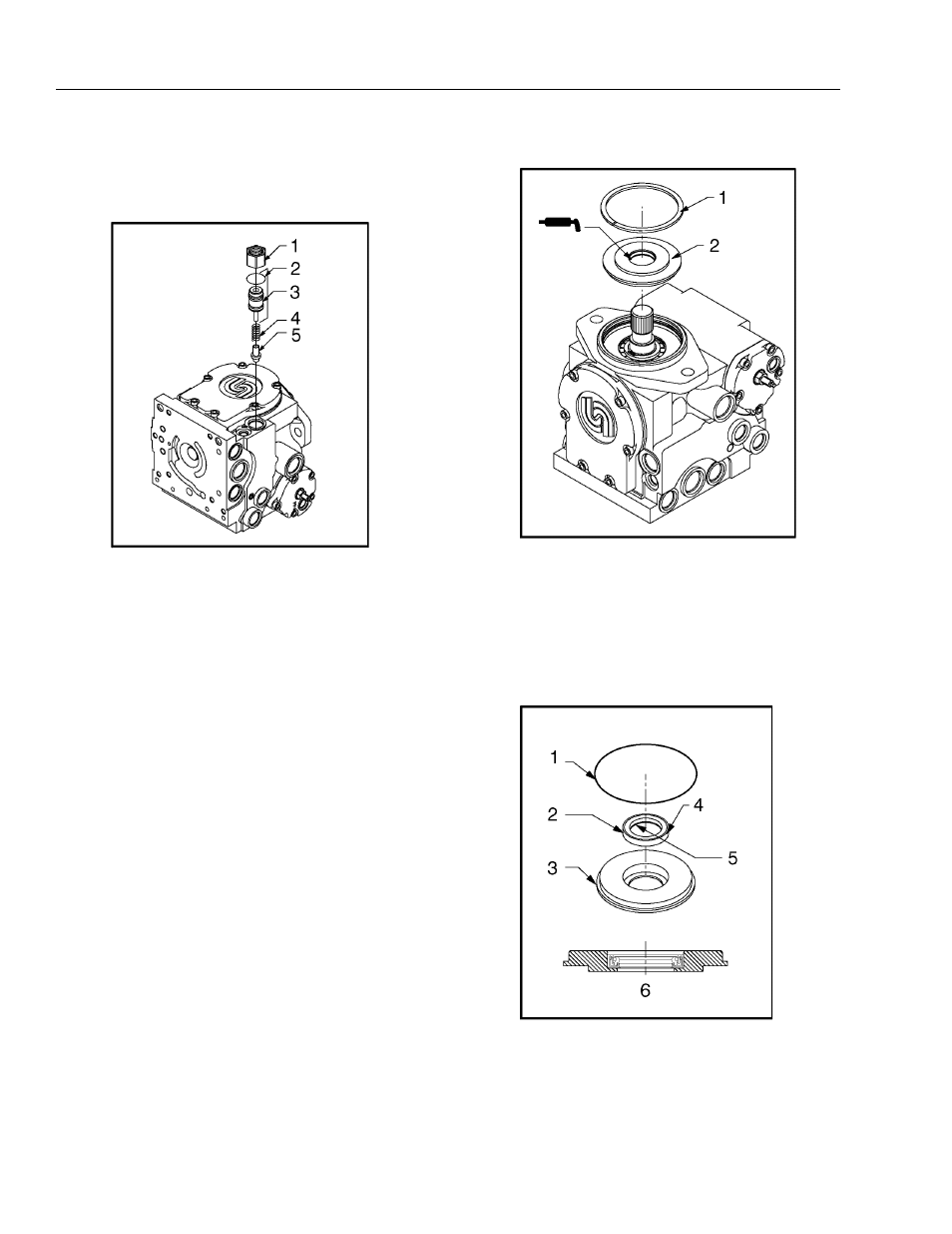
1. Lock Nut
2. O-Ring
3. Plug
4. Spring T-Seal
5. Poppet
Figure 5-36. Screw Adjustable Charge Relief
Valve Components
1. Retaining Ring
2. Seal Carrier Assembly
Figure 5-37. Shaft Seal Components
1. O-Ring
2. Seal
3. Seal Carrier
4. Sealant may be used on outside diameter
5. Inside Lip (face down)
6. Press Seal to Bottom of Seal Carrier
Figure 5-38. Installation of Shaft Seal