Cluster gear punch marks -39 – JLG 450A_AJ Series II Service Manual User Manual
Page 89
SECTION 3 - CHASSIS & TURNTABLE
3121180
– JLG Lift –
3-39
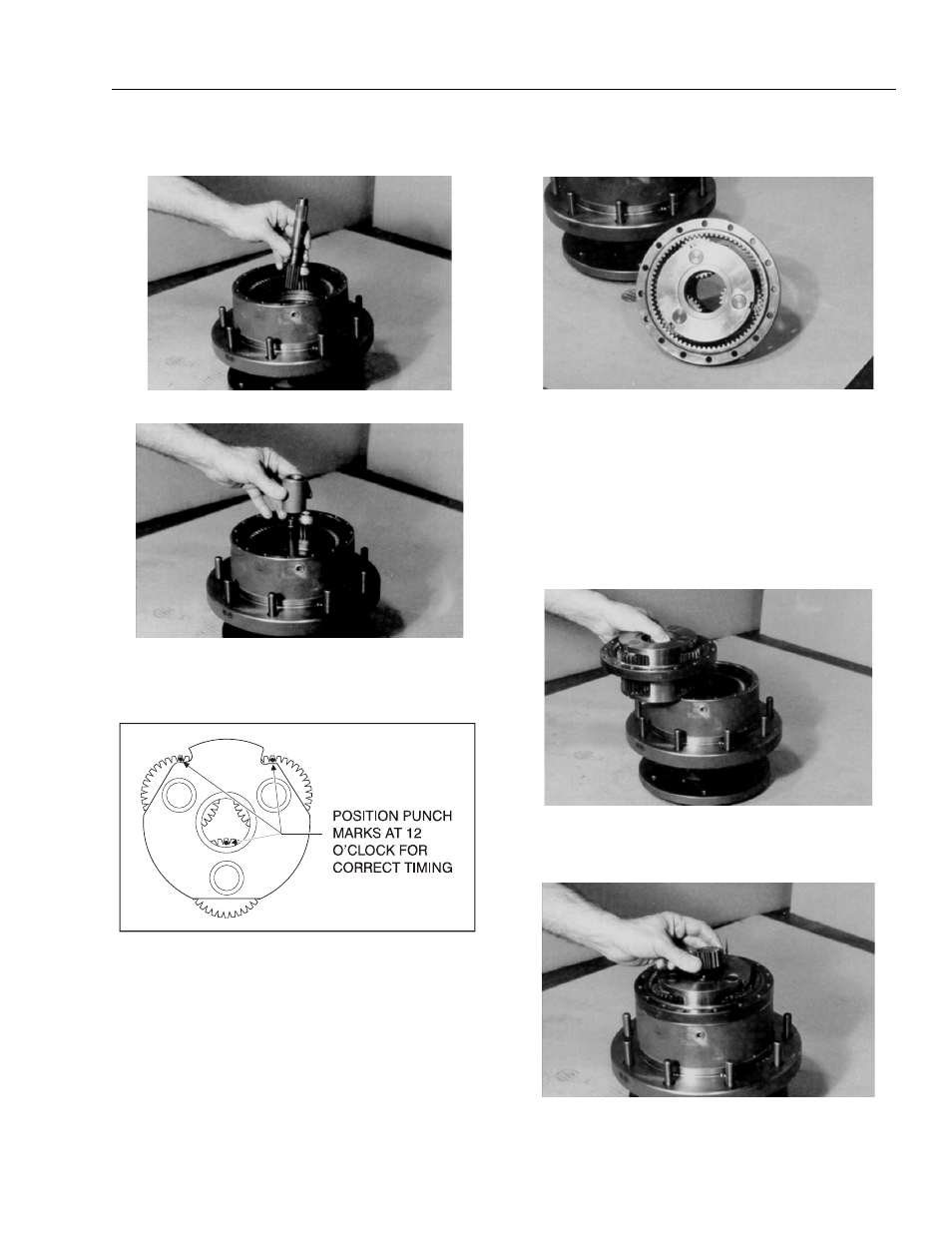
9. With large splined end down, place input shaft sub-
assembly (7) into spindle (1A).
10. Place thrust spacer (9) onto input shaft (7).
11. Set carrier sub-assembly (3) on a flat work surface
so large ends of cluster gears (3F) face up. Locate
punch marks on face of each cluster gear (3F) and
position them at 12 o’clock.
12. With “X” marked side facing up, place ring gear (4)
around cluster gears (3F).
NOTE: This will hold punch marks in position while installing
carrier into hub.
13. Place carrier sub assembly (3) and ring gear (4)
together into mesh with internal gear (2), aligning
“X” marked shoulder bolt hole in ring gear (4) over
one of the shoulder bolt holes in hub. Mark location
of shoulder bolt holes on outside of ring gear and
hub.
NOTE: You may lift ring gear off hub to align shoulder bolt
holes. Ring gear and carrier are installed together
only to keep punch marks on carrier in place.
14. With internal splines facing up (counterbore end facing
down), place input gear (8) into mesh with carrier sub-
assembly (3).
Figure 3-22. Cluster Gear Punch Marks