JLG X20JP - X600AJ Service Manual User Manual
Page 326
SECTION 7 - BASIC ELECTRICAL INFORMATION & SCHEMATICS
3121623
– JLG Lift –
7-1
SECTION 7. BASIC ELECTRICAL INFORMATION & SCHEMATICS
7.1 DESCRIPTION FOR MODELS
X17JP/X500AJ - X20JP/X600AJ
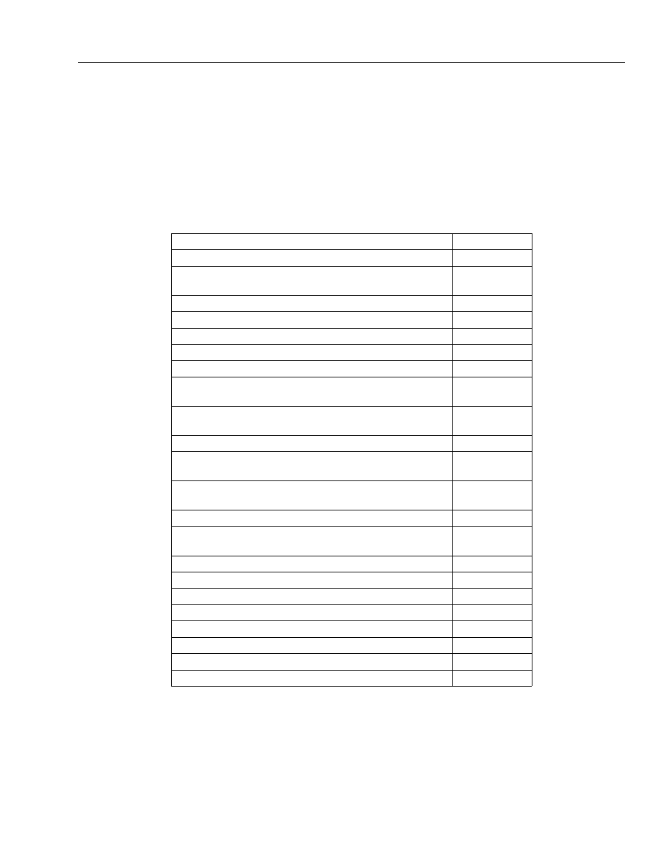
Table 7-1. X17JP/X500AJ - X20JP/X600AJ
How to read the electric wiring diagrams
Photocells – Safety Exclus
A
Slew proximity – 1° arm switch – Stabilizers pressure
sensors
B
Outriggers switches
C
Can Network - Cylinder position sensor – Modem
D
Ropes switch - Jib position switch – Pedal – Load cell
E
Ground position control box
F
Aerial safety line
G
Emergency descend electro valves – Widening cylin-
der sensors - Optionals
H
Ground part: Tracks – Undercarriage widening – 2°
speed – Proportional electro valves
I
Ground part: Outriggers – Electric diverter
J
Aerial part: Basket levelling – Basket rotation – Jib –
Proportional electro valve
K
Aerial part: 1° Cylinder - 2° cylinder – Extension - Rota-
tion
L
Engine diesel versions: RPM regulation system
M
Engine diesel Perkins 2 cylinders: Sensors and electro
stop
N
Engine diesel Perkins 2 cylinders: Start and sparks
O
Engine Diesel Hatz 1 cylinder
P
Engine Gasoline Honda 1 cylinder
Q
12 Volt power supply
R
120/230 Volt Line
S
Components location
T
Components abbreviation meaning
U
Connectors layout
V