JLG X20JP - X600AJ Service Manual User Manual
Page 126
SECTION 3 - CHASSIS & TURNTABLE
3-102
– JLG Lift –
3121623
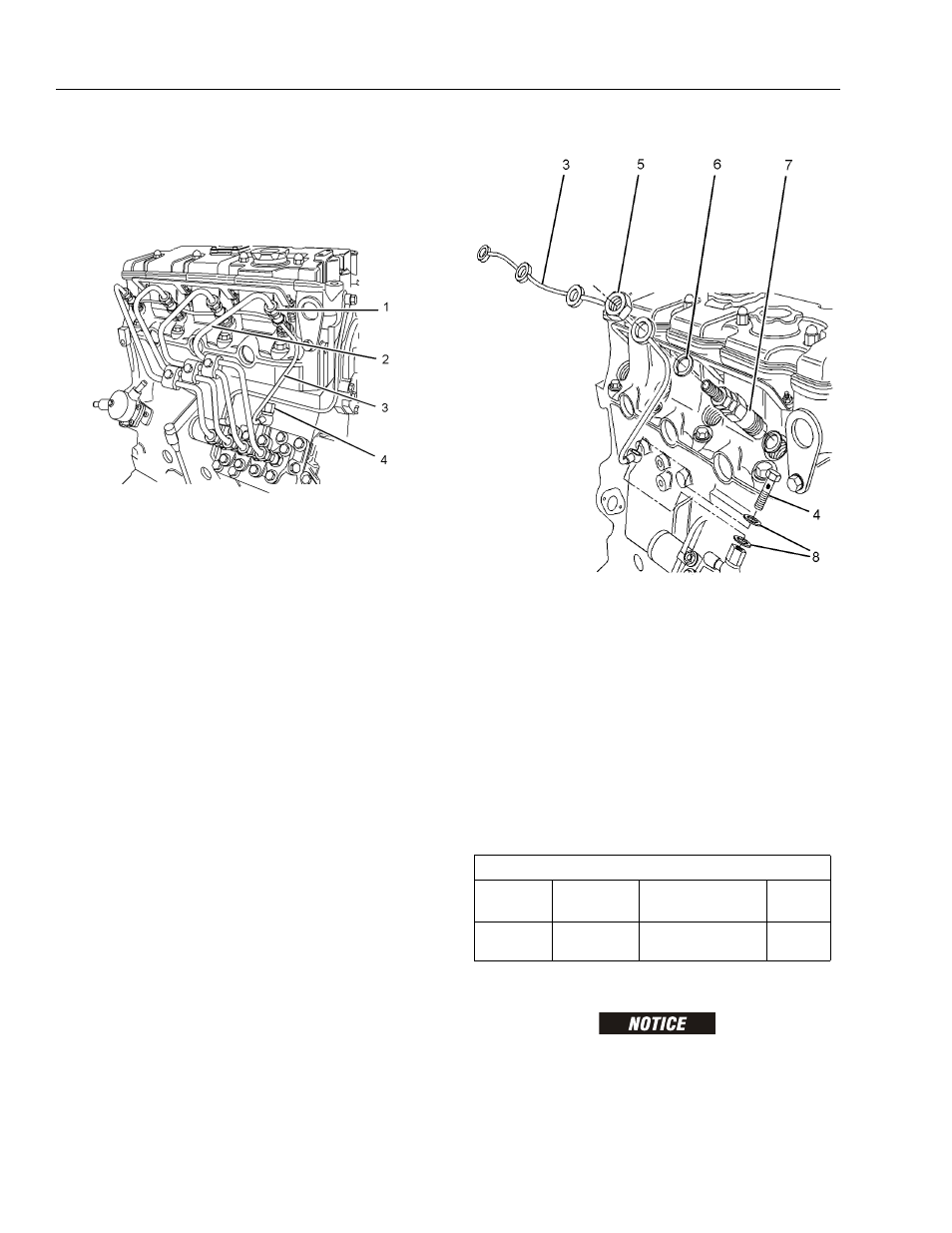
NOTE: Place identification marks on all tube assemblies for
installation. Plug all lines and tube assemblies in order to
prevent contamination.
8. Turn the fuel supply to the OFF position.
9. Disconnect nuts (1) for fuel injection lines (2) from
the fuel injectors.
10. Disconnect nuts (1) for fuel injection lines (2) from
the fuel injection pump.
11. Remove fuel injection lines (2) from the engine as a
unit.
12. Use suitable caps in order to plug the open ports of
the fuel injection pump immediately.
For engines with a rigid fuel return line, remove banjo bolt
(4) from fuel return line (3). Remove washers (8).
The 402D-05, 403D-07, 403D-11 and 404D-15 engines
have a flexible fuel return hose.
For engines with a flexible fuel return hose, disconnect the
hose from the fuel injection pump.
13. Remove nuts (5) from fuel injectors (7).
NOTE: For engines with a rigid fuel return line, ensure that the
fuel return line is not distorted when the nuts are loos-
ened.
14. Remove fuel return line (3) and washers (6) from fuel
injectors (7).
15. Use suitable caps in order to plug the fuel injectors
immediately.
INSTALLATION PROCEDURE
KEEP ALL PARTS CLEAN FROM CONTAMINANTS. CONTAMI-
NANTS MAY CAUSE RAPID WEAR AND SHORTENED COMPONENT
LIFE.
Required Tools
Tool
Part
Number
Part Name
Qty
A
27610294
Injector Pipe Nut
Tool
1