Motor and brake assembly, Motor and brake assembly -21, Motor & brake disassembly -21 – JLG 3246ES Service Manual User Manual
Page 57
SECTION 3 - CHASSIS & SCISSOR ARMS
3121166
– JLG Lift –
3-21
Motor and Brake Assembly
NOTE: Applies only to:
USA machines built prior to S/N 0200118041,
Belgium machines built prior to S/N 1200001487.
1.
Remove back sealing cover from motor if it is not
already removed.
2.
Remove retention bolt and washer from the motor
shaft end. Do not let the armature shaft fall out
of the open end of the motor.
3.
Open up Brake Kit. It should have a brake housing,
brake disc, and three spacers.
4.
Install Brake disc onto splined end of motor shaft.
NOTE: Keep the brake disc clear of any oil or grease.
5.
Reinstall the retention bolt and washer into the
shaft end to keep the armature in the motor.
6.
Install the brake housing onto motor end cap; use
the included spacers to space the brake housing
from the motor end. There may be motor wires in
the way. Push them aside to mount the brake.
7.
Fasten with 3 Bolts to a torque of 4 - 5 ft.-lbs.
8.
Remove the disengage bolts from the brake hous-
ing and install them into the tapped holes in the
motor end cap for storage.
9.
Connect the connector (not shown) from the
brake housing to the connector from the motor.
10.
If not already done, remove thru bolts from motor.
11.
Grease the motor O’ring (31) and install in the
groove of the gearbox assembly. Also, apply
grease to the lip of the motor shaft seal (17) in the
gearbox.
12.
Lift motor and line up the thru bolt holes with the
tapped holes of the gearbox so that the motor ori-
ents with the strain relief behind the neck of the
spindle.
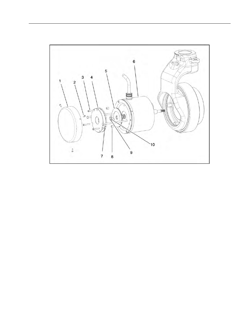
13.
Brake Cover
14.
Disengage Bolts
15.
Socket Head Screws
16.
Brake Housing
17.
5. Disc Brake
18.
Motor
19.
Thru Bolts
20.
Spacers
21.
Retention Bolt
22.
Washer
Figure 3-18. Motor & Brake Disassembly