7 pump/motor, Pump/motor -6 – JLG 3246ES Service Manual User Manual
Page 108
SECTION 4 - HYDRAULICS
4-6
– JLG Lift –
3121166
4.7
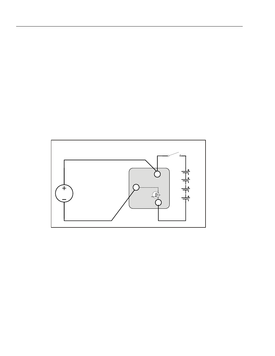
PUMP/MOTOR
Theory of Operation
The Power Module (see Figure 3-32., Sevcon Power
Module Location on page 3-38) is essentially a "low-
side" switch for the pump motor. The positive terminal
of the pump is tied to Battery Positive after the Line
Contactor. The negative terminal of the pump connects
to the P Terminal of the Power Module, which switches
current through MOSFET transistors to the Battery Neg-
ative.
For variable speed pump operation, the MOSFET transis-
tors switch On and Off at high frequencies (16kHz). The
Duty Cycle is varied to control the voltage applied to the
pump motor. When the MOSFET's spend 50% of the
period On and 50% Off, approximately ½ of the avail-
able Battery Voltage will be applied to the pump motor.
Similarly, the MOSFET are On continuously (100% Duty
Cycle) to apply all available Battery Voltage to the pump
motor (as in Lift Up at full speed).
When the Control System is energized, the voltage at
the P Terminal will be approximately +24V (referenced
to -B) when the pump is static. The P Terminal will be
approximately at +1V (referenced to -B) when the pump
is running at full speed (Lift Up from Ground Mode).
-B
P
+B
Series DC
Pump Motor
24V
Line Contactor
Power Module