Lift cylinder assembly -17 – JLG 3246ES Service Manual User Manual
Page 119
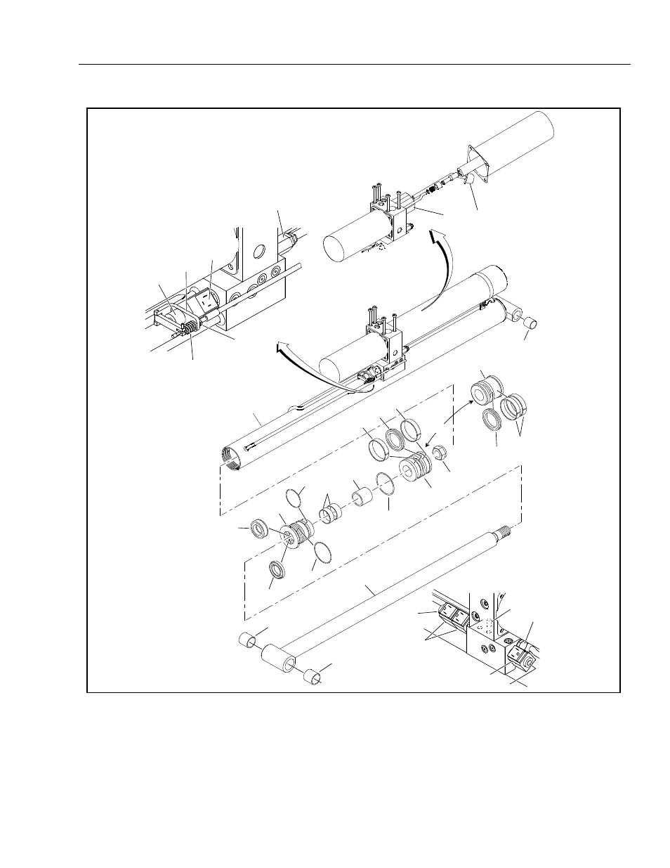
SECTION 4 - HYDRAULICS
3121166
– JLG Lift –
4-17
1. Proportional Valve
2. Emergency Release Assy.
3. Coil
4. Relief Valve
5. Pump
6. Filter
7. Spring
8. Jam Nut
9. Bushing
10. Barrel
11. Wear Ring
12. Seal
13. Locknut
14. Piston
15. O-ring
16. Seal
17. Head
18. O-ring
19. Wear Ring
20. Spacer
21. Wiper
22. O-ring
23. Bushing
24. Cylinder Rod
25. Check Valve
26. Dowel Pin
27. Directional Control Valve
28. Coil
29. Directional Control Valve
Figure 4-13. Lift Cylinder Assembly
OPPOSITE SIDE OF
CYLINDER PORT BLOCK
1
2
3
4
8
7
9
10
16
17
18
19
21
22
20
15
11
12
12
11
11
14
14
13
27
28
25
28
29
24
23
23
OR
1930ES
ONLY
26
6
5
This manual is related to the following products: