JLG 3246ES Service Manual User Manual
Page 138
SECTION 5 - JLG CONTROL SYSTEM
5-18
– JLG Lift–
3121166
Help messages with the 6-6 flash code indicate vehicle communication (CANbus) problems. These faults shall not be latched. Normal operation shall
resume if difficulty is resolved.
6 6
CANBUS FAILURE: POWER MODULE
The control system failed to receive messages from the Power
Module.
Power Module Message – Status (0x24) not received for
1000mS or Power Module is reported a “CANbus Bus Difficulty”
Fault Code (0x09).
Drive, Steer, & Lift Up Prevented.
Check wiring at the ground con-
trol box and power module.
Recycle power to clear difficulty.
6 6
CANBUS FAILURE: PLATFORM MODULE
In Platform Mode, the control system failed to receive mes-
sages from the platform module.
Digital Input Message – Motion (0x00) not received for
1000mS AND Platform Mode selected. Retained until power is
re-cycled.
All Platform functions Prevented. Normal operation from
Ground Mode.
Check wiring at the platform
and ground control boxes. Check
wiring along scissor arms lead-
ing up to Platform.
6 6
CANBUS FAILURE: LOAD SENSING SYSTEM MODULE
With the Load Sensing System enabled, the control system
failed to receive messages from the Load Sensing System Mod-
ule.
LSS Module Message – Load Cell Message (0x80) not received
for 1000mS AND [Machine Setup’s LOAD set to 1=CUTOUT PLT
OR 2=CUTOUT ALL]. Retained until power is re-cycled.
Vehicle assumed to be Overloaded.
Check wiring at the Load Sens-
ing System Module and along
scissor arms leading up to plat-
form.
6 6
ACCESSORY CAN COMMUNICATION LOST
A JLG Accessory Module has failed to maintain CANbus com-
munications with the ground module.
The control system received Accessory Message – Control 1
from an Accessory Module, but failed to receive another within
1000mS. Retained until power is re-cycled.
No motion interlocks.
Refer to documentation for the
JLG Accessory to clear difficulty.
Help messages with the 6-7 flash code indicate JLG accessory problems. These faults shall not be latched. Normal operation shall resume if difficulty
is resolved.
6 7
ACCESSORY FAULT
A JLG Accessory Module has encountered a fault condition and
reported it via the host control system.
Accessory Message – Control 1’s Request Accessory Fault flag is
set to YES. Retained or cleared based on status of flag.
No motion interlocks.
Refer to documentation for the
JLG Accessory to clear difficulty.
Help messages with the 7-7 flash code indicate motor problems.
7 7
OPEN-CIRCUIT DRIVE MOTOR FIELD WIRING
The Power Module detected an error in the power wiring (F1 &
F2 Terminals) for the drive motors.
The Power Module is reporting a “Field Open Circuit” Fault
Code (16d). Retained until power is re-cycled.
Drive & Steer Prevented
Check power wiring and re-
cycle power to clear difficulty.
Help messages with the 8-x flash codes indicate problems with the platform load sensing system. The second digit of the flash code is used to indi-
cated channel.
8 1
LSS CELL #1 ERROR
Cell #1’s Bridge <2Vdc, >3Vdc, or could the LSS Module could
not read Cell #1’s Internal Memory.
8-1 Flash Code
LSS Module Message – Status Message (0x81) is reporting
“CELL 1 ERROR” AND [Machine Setup’s LOAD is set to 1=CUT-
OUT PLT OR 2=CUTOUT ALL].
Vehicle assumed to be Overloaded.
This situation indicates that the
sensor is unplugged, or the sen-
sor is damaged.
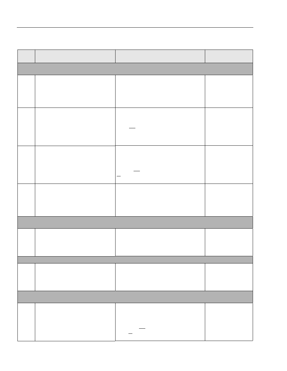
Table 5-2. Flash Code Listing
Flash
Code
Help Message
Cause
Possible Resolve