1 line contactor open circuit, 1 line contactor open circuit -9, 5 function prevented – JLG 3246ES Service Manual User Manual
Page 162
SECTION 6 - DIAGNOSTIC TROUBLE CODES
6-10
– JLG Lift –
3121166
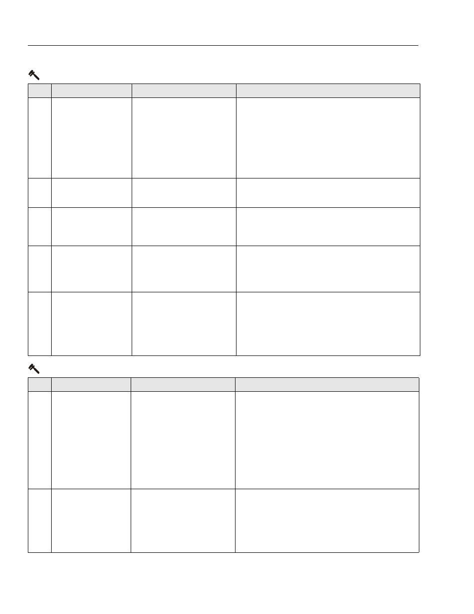
258
DRIVE & LIFT PRE-
VENTED - BRAKES ELEC-
TRICALLY RELEASED
FOR TOWING
Manual brake release mode is
activated with the switch in the
battery box near the ground
control box. Drive or lift is not
possible.
• Push manual brake release switch again or cycle
power to clear manual brake release mode.
• Check if the brake release switch is obstructed or
jammed.
• Check the brake release switch signal and wiring to
the ground board. The switch input (24V) is from
ground board terminal J1-19, and its output (24V
when closed) is to ground board terminal J1-20.
• Replace ground board.
259
MODEL CHANGED -
HYDRAULICS SUS-
PENDED - CYCLE EMS
The model selection has been
changed.
• Check ANALYZER -> MACHINE SETUP -> MODEL NUM-
BER.
• Replace ground board.
2510 DRIVE PREVENTED -
BRAKES NOT RELEASING
While driving on a level surface,
armature current was > 150A for
five seconds. Brakes assumed to
not be releasing properly.
• Ensure vehicle is not stuck on something preventing
movement.
• Check / repair drive motor wiring, brakes or mechani-
cal issues.
2511 ELEV ANGLE SENSOR
FAULTY - NOT MOUNTED
The input voltage from the ele-
vation angle sensor indicates
the elevation angle sensor is not
mounted.
• Check that the elevation angle sensor is securely
mounted.
• Check that the elevation angle sensor mechanisms
are intact.
• Replace elevation angle sensor.
2512 ELEV ANGLE SENSOR
NOT DETECTING
CHANGE
The input voltage from the ele-
vation angle sensor did not
change while vehicle was lifting
up.
• Check that the elevation angle sensor is securely
mounted.
• Check elevation angle sensor is not jammed or
obstructed.
• If there are any other elevation angle sensor, joystick,
or lift up faults, troubleshoot them before continuing.
• Replace elevation angle sensor.
3-1 Line Contactor Open Circuit
DTC
FAULT MESSAGE
DESCRIPTION
CHECK
311
OPEN CIRCUIT LINE
CONTACTOR
The power modules line contac-
tor did not close when ener-
gized. Drive, steer and lift up
prevented.
• Check contactor main contact wiring to battery (+)
terminal and power controller terminal B+.
• Contactor solenoid resistance should measure about
52 Ohms.
• Check contactor solenoid wiring to power module 12
position connector terminal 8 and ground board ter-
minal J1-19.
• Check that power module 12 position connector ter-
minal 8 goes from 24V to near 0V while contactor
should be closing. If this happens replace contactor.
• Replace the line contactor.
312
CONTACTOR DRIVER
PERMANENTLY OFF
The power modules line contac-
tor drive circuitry failed to ener-
gize when requested. Drive,
steer and lift up prevented.
• Check continuity between contactor connector pin 1
and ground board socket J1-19.
• Contactor solenoid resistance should measure about
52 Ohms.
• Check continuity between contactor connector pin 2
and power module connector socket 8.
• Replace power module.
2-5 Function Prevented
DTC
FAULT MESSAGE
DESCRIPTION
CHECK