4 installation, Installation – Eppendorf InjectMan NI 2 User Manual
Page 15
68
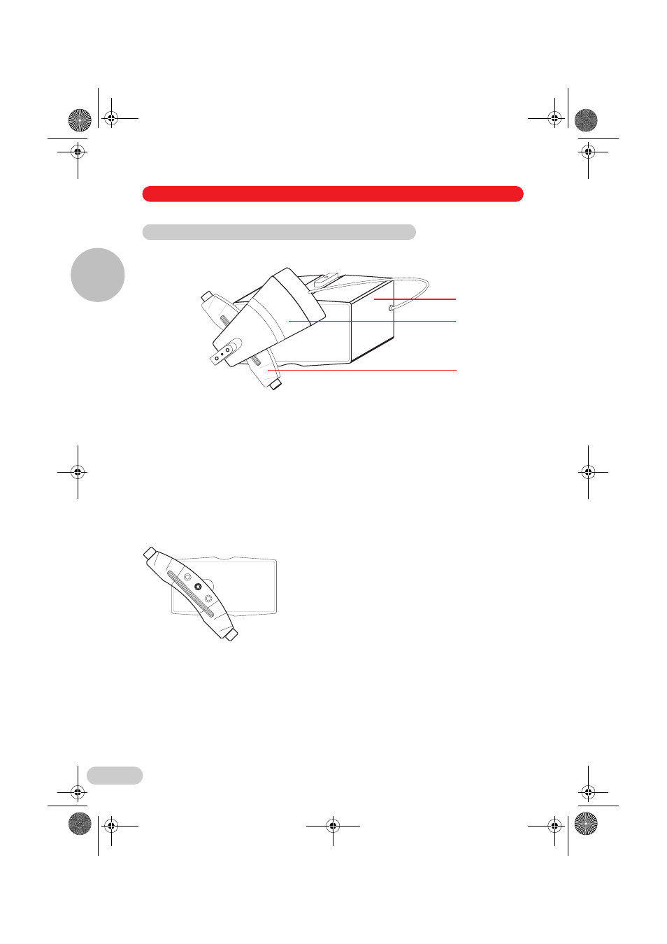
4.2.1 Components of the module unit
Fig. 3: Module unit, assembled (here right side mounted)
1 Motor unit for horizontal movements (X/Y module)
2 Axial motor unit (A module, without tool mount)
3 A module arc guide
4.2.2 Angle guide
The A module is attached by bolting on the angle guide.
Depending on the mounting point of the angle guide, injection angles between 60° and 30° can
be set.
For the sake of clarity, the A module is not shown.
Example:
The angle guide is attached to the X/Y module in the
centre hole, corresponding to 45°. The A module can
be adjusted to between 55° and 35° (45°±10°) by
turning the spindle.
4.2 Assembling the module unit
10
10
5
5
1
2
3
10
10
10
10
5
5
4 Installation
Installation
4
04_Install_en.fm Seite 68 Donnerstag, 6. Dezember 2012 1:32 13
- epMotion 96 (76 pages)
- epMotion 5070 (100 pages)
- epMotion 5075 (130 pages)
- Centrifuge 5427 R (64 pages)
- Centrifuge 5427 R (104 pages)
- White Paper 14 (8 pages)
- Rolling Cabinet (34 pages)
- Mastercycler nexus (118 pages)
- Mastercycler nexus (142 pages)
- Concentrator plus (New Design) (48 pages)
- Concentrator plus (43 pages)
- Easypet 3 (38 pages)
- Xplorer (74 pages)
- Xplorer Adjustment (26 pages)
- AF2200 Plate Reader (72 pages)
- AF2200 Plate Reader (78 pages)
- G0.5 µPlate (32 pages)
- BioSpectrometer basic (104 pages)
- BioSpectrometer kinetic (106 pages)
- BioSpectrometer fluorescence (102 pages)
- Micro Test Tubes (5 pages)
- Microplates (10 pages)
- PiezoXpert (34 pages)
- Eporator (38 pages)
- MiniSpin (20 pages)
- MiniSpin (25 pages)
- 5702 Centrifuge (27 pages)
- 5702 Centrifuge (32 pages)
- Centrifuge 5702 (32 pages)
- C5702 RH Centrifuge (32 pages)
- 5418 Centrifuge (80 pages)
- 5418 Centrifuge (48 pages)
- 5424 Centrifuge (71 pages)
- 5424 Centrifuge (44 pages)
- 5430 Centrifuge (88 pages)
- 5430 Centrifuge (130 pages)
- 5804 Centrifuge (129 pages)
- 5804 Centrifuge (95 pages)
- 5804 Centrifuge (127 pages)
- TransferMan4 r (102 pages)
- TransferMan4 m (96 pages)
- InjectMan 4 (100 pages)
- InjectMan NI 2 (16 pages)
- PatchMan NP 2 (53 pages)