Caution, Warning, Setup switches (sw1) – Bryant Bruant 4 Way Gas 355AAV User Manual
Page 45: Step 3 — prime condensate trap with water, Step 4 — purge gas lines, Step 5 — sequence of operation
45
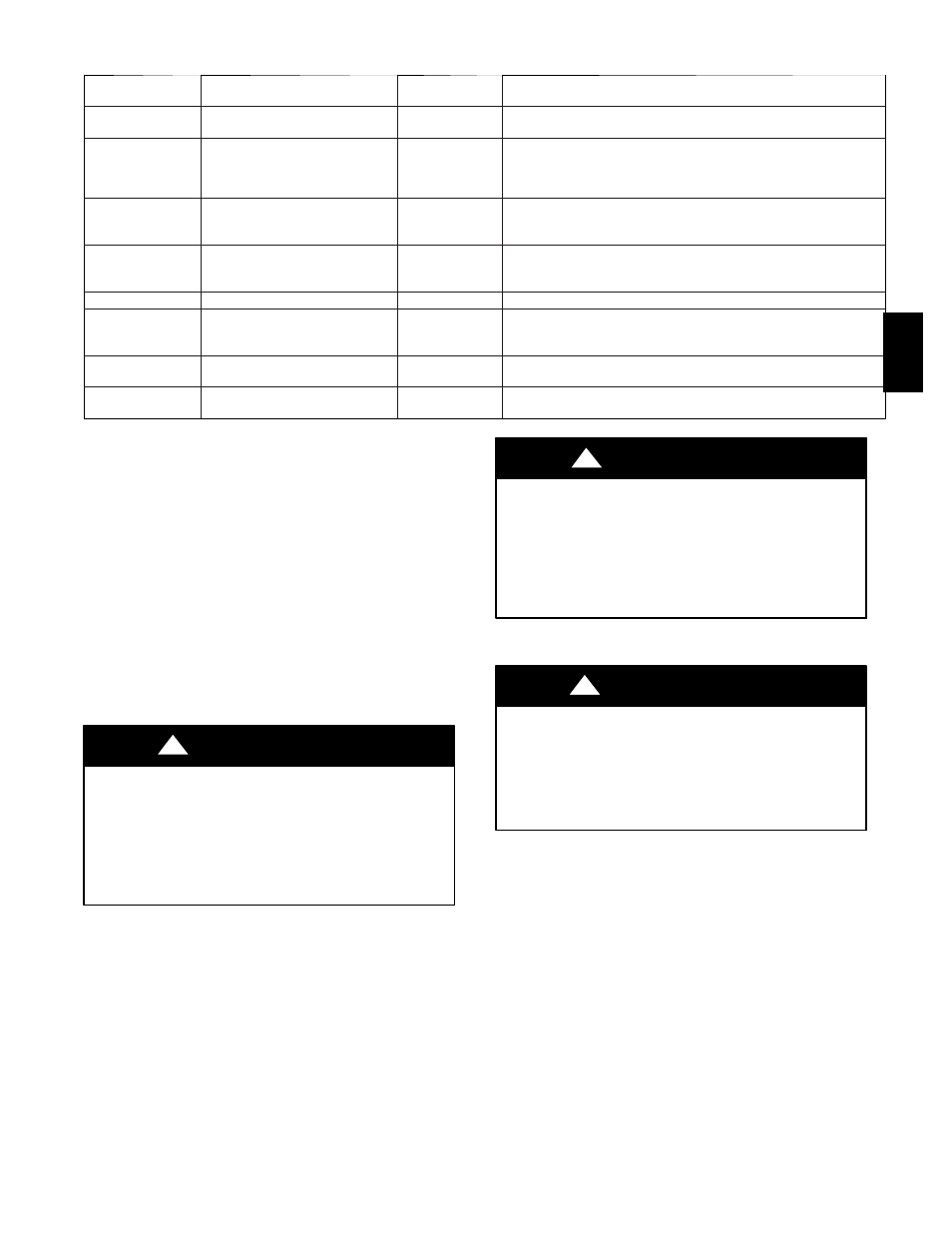
Table 13 – Furnace Setup Switch Description
SETUP SWITCH
NO.
SWITCH NAME
NORMAL
POSITION
DESCRIPTION OF USE
SW1---1
Status Code Recovery
OFF
Turn ON to retrieve up to 7 stored status codes for troubleshooting
assistance when R thermostat lead is disconnected.
SW1---2
Adaptive Heat Mode
OFF
Allows 2---stage operation with a single stage thermostat. Turn ON
when using 2 stage thermostat to allow Low Heat operation when
R to W/W1 closes and High Heat operation when R to W/W1 and
W2 close.
SW1---3
Low Heat Rise Adjust
OFF
Turn ON to increase Low Heat airflow by 18 percent. This com-
pensates for increased return air temperature caused with bypass
humidifier.
SW1---4
Comfort/Efficiency Adjustment
ON
Turn ON to decrease Low Heat airflow by 7 percent and High Heat
airflow 8 percent for maximum comfort. On 040 unit will decrease
Low---Heat Airflow 11 percent and High---Heat Airflow 10 percent.
SW1---5
CFM per ton adjust
OFF
Turn ON for 400 CFM per ton. Turn OFF for 350 CFM per ton.
SW1---6
Component Self---Test
OFF
Turn ON to initiate Component Self---Test for troubleshooting as-
sistance when R thermostat lead is disconnected. Turn OFF when
Self---Test is completed.
SW1---7
Blower OFF delay
ON or OFF
Control blower Off Delay time. Used in conjunction with SW1---8.
See Table 14.
SW1---8
Blower OFF delay
ON or OFF
Control blower Off Delay time. Used in conjunction with SW1---7.
See Table 14.
SETUP SWITCHES (SW1)
The furnace control has 8 setup switches that may be set to meet
the application requirements. Position these setup switches for the
appropriate requirement.
1. Remove main furnace door and blower access panel.
2. Locate setup switches on furnace control. (See Fig. 37.)
3. See Table 13 for setup switch description. (See Fig. 36 and
48.)
4. Replace main furnace door and blower access panel.
NOTE: If a bypass humidifier is used, setup switch SW1--3 (Low
HEAT Rise Adjust) should be in ON position. This compensates
for the increased temperature in return air resulting from bypass.
NOTE:
If modulating dampers are used, blower motor
automatically compensates for modulating dampers.
Step 3 — Prime Condensate Trap With Water
UNIT MAY NOT OPERATE
Failure to follow this caution may result in intermittent unit
operation or performance satisfaction.
Condensate trap must be PRIMED or proper draining may not
occur. The condensate trap has 2 internal chambers which can
ONLY be primed by pouring water into the inducer drain side
of condensate trap.
CAUTION
!
1. Remove upper inducer housing drain connection cap. (See
Fig. 49.)
2. Connect field--supplied 1/2--in. (13 mm) ID tube to upper
inducer housing drain connection.
3. Insert field--supplied funnel into tube.
4. Pour 1 quart of water into funnel/tube. Water should run
through inducer housing, overfill condensate trap, and flow
into open field drain. (See Fig. 50.)
5. Remove funnel and tube from inducer housing and replace
drain connection cap and clamp.
Step 4 — Purge Gas Lines
If not previously done, purge the lines after all connections have
been made and check for leaks.
FIRE AND EXPLOSION HAZARD
Failure to follow this warning could result in personal injury,
death or property damage.
Never purge a gas line into a combustion chamber. Never test
for gas leaks with an open flame. Use a commercially available
soap solution made specifically for the detection of leaks to
check all connections.
!
WARNING
Step 5 — Sequence of Operation
UNIT MAY NOT OPERATE
Failure to follow this caution may result in intermittent unit
operation.
Furnace control must be grounded for proper operation, or
control will lock out. Control is grounded through
green/yellow wire routed to gas valve and burner box screw.
CAUTION
!
Using schematic diagram, follow sequence of operation through
different modes. (See Fig. 36.) Read and follow wiring diagram
carefully.
NOTE: If a power interruption occurs during a call for heat
(W/W1 or W/W1--and--W2), the control will start a 90--second
blower--only ON period two seconds after power is restored, if the
thermostat is still calling for gas heating. The amber LED light will
flash code 12 during the 90--second period, after which the LED
will be ON continuous, as long as no faults are detected. After the
90--second period, the furnace will respond to the thermostat
normally.
The blower door must be installed for power to be conducted
through the blower door interlock switch ILK to the furnace
control CPU, transformer TRAN, inducer motor IDM, blower
motor BLWM, hot--surface igniter HSI, and gas valve GV.
355A