Installation, Combination of indoor and outdoor air, Step 1 — leveling legs (if desired) – Bryant Bruant 4 Way Gas 355AAV User Manual
Page 20: 355a
20
1 SQ IN .
PER
4000
BTUH*
DUCTS
TO
O UTDOORS
1 SQ IN.
PER 4000
BTUH*
C
IRCULA
TING
AIR DUCTS
VENT
THR OUGH
R OOF
D
B
A
C
E
1 SQ IN.
PER 4000
BTUH*
DUCT
TO
OUTDOORS
CIRCULA TING AIR DUCT S
1 SQ IN.
PER 2000
BTUH*
1 SQ IN.
PER 2000
BTUH*
DUCT S
TO
OUTDOORS
12
″ MAX
12
″ MAX
12
″ MAX
12
″
MAX
12
″
MAX
OUTDOORS
1 SQ IN .
PER
4000
BTUH*
F
G
CLEARANCE IN FRONT
OF COMB
USTION AIR
OPENINGS SHALL BE
AT LEAST 3 IN
.
(305mm)
(305mm)
(305mm)
(305mm)
(305mm)
(76mm)
*Minimum dimensions of 3 in. (76 mm).
Use any of the following combinations of openings:
A & B C & D D & E F & G
A03174
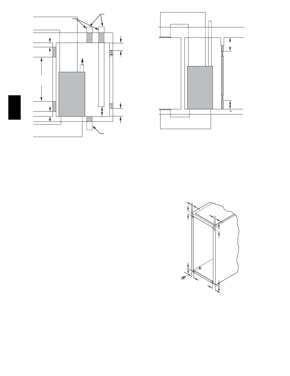
Fig. 19 -- Air for Combustion, Ventilation, and Dilution for
Outdoors
When combustion air ducts are used, they must be of the same
cross sectional area as the free area of the openings to which they
connect. The minimum dimension of ducts must not be less than 3
in. (76 mm).
Combination of Indoor and Outdoor Air
1. Indoor openings shall compy with the Indoor Combustion
Air Method below and,
2. Outdoor openings shall be located as required in the
Outdoor Combustion Air Method mentioned previously
and,
3. Outdoor openings shall be sized as follows:
a. Calculate the Ratio of all Indoor Space volume divided
by required volume for Indoor Combustion Air
Method below.
b. Outdoor opening size reduction Factor is 1 minus the
Ratio in a. above.
c. Minimum size of Outdoor openings shall be the size
required in Outdoor Combustion Air Method above
multiplied by reduction Factor in b. above. The
minimum dimension of air openings shall be not less
than 3 in. (76 mm).
INSTALLATION
Step 1 — Leveling Legs (If Desired)
When furnace is used in upflow position with side inlet(s), leveling
legs may be desired. (See Fig. 21.) Install field--supplied,
corrosion--resistant 5/16--in. (8 mm) machine bolts and nuts.
NOTE: The maximum length of bolt should not exceed 1--1/2 in.
(38 mm).
1. Position furnace on its back. Locate and drill a 5/16--in. (8
mm) diameter hole in each bottom corner of furnace. (See
Fig. 21.) Holes in bottom closure panel may be used as
guide locations.
CIRCULATING AIR
DUCTS
6" MIN
(FRONT)
Ü
CIRCULATING AIR DUCTS
VENT THROUGH ROOF
1 SQ IN.
PER 1000
BTUH* IN DOOR
OR
WALL
12" MAX
1 SQ IN.
PER 1000
BTUH* IN DOOR
OR
WALL
12" MA X
UNCONFINED
SPACE
INTERIOR
HEATED
SPACE
CLEARANCE IN FRONT OF COMBUSTION AIR
OPENINGS SHALL
BE A
T LEAST 3 IN.
(305mm)
(152mm)
(305mm)
* Minimum opening size is 100 sq in. with minimum dimensions of 3 in. (76 mm)
† Minimum of 3 in. (76 mm) when type-B1 vent is used.
A03175
Fig. 20 -- Air for Combustion, Ventilation, and Dilution from
Indoors
2. For each hole, install nut on bolt and then install bolt and
nut in hole. (Install flat washer if desired.)
3. Install another nut on other side of furnace base. (Install flat
washer if desired.)
1
3
/
4
″
1
3
/
4
″
1
3/
4
″
1
3/
4
″
5/
16
″
5
/
16
″
5/
16
″
5/
16
″
(44mm)
(8mm)
(44mm)
(8mm)
(8mm)
(8mm)
(44mm)
(44mm)
A89014
Fig. 21 -- Leveling Legs
4. Adjust outside nut to provide desired height, and tighten inside
nut to secure arrangement.
NOTE: Bottom closure must be used when leveling legs are used.
See Bottom Closure Panel section.
Step 2 — Installation in Upflow or Downflow
Applications
NOTE: This furnace is approved for use on combustible flooring.
Special base is not required when this furnace is installed on
355A