355a, Dimensions -- in. (mm) – Bryant Bruant 4 Way Gas 355AAV User Manual
Page 4
4
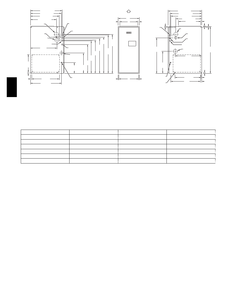
NO TES: 1. Minimum retur n-air openings at fur nace , based on metal duct. If fle x duct is used,
see fle x duct manuf acturerí s recommendations f or equiv alent diameters .
2. Minimum retur n-air opening at fur nace:
a. F or 800 CFM–16-in. (406mm) round or 14
1
/
2
(368 mm)x 12-in. (305 mm) rectangle
.
b. F or 1200 CFM–20-in. (508mm) round or 14
1
/
2
(368mm)x 19
1
/
2
-in. (495mm) rectangle
.
c. F or 1600 CFM–22-in. (559mm) round or 14
1
/
2
(368mm)x 23
1
/
4
-in. (591mm) rectangle
.
d. F or airflo w requirements abo v e 1800 CFM, see Air Deliv er y tab le in Product Data
literature f or specific use of single side inlets . The use of both side inlets , a
combination of 1 side and the bottom, or the bottom only will ensure adequate
retur n air openings f or airflo w requirements abo v e 1800 CFM .
17
5
⁄
16
"
24
1
⁄
2
"
27
9
⁄
16
"
TYP
27
5
⁄
8
"
29
11
⁄
16
"
TYP
30
13
⁄
16
"
32
5
⁄
8
"
TYP
33
1
⁄
4
"
TYP
CONDENSA TE
DRAIN TRAP
LOCA TION
(AL TERNA TE
UPFL OW )
7
⁄
8
-IN . DI A (22mm)
A CCESSOR Y
PO WER ENT RY
7
⁄
8
-IN . DI A (22mm)
PO WER CONN
CONDENSA TE DRAI N
TRAP LOCA TION
(DO WNFLO W &
HORIZONT AL LEFT )
26
15
⁄
16
"
24
1
⁄
2
"
22
5
⁄
16
"
2-IN . (51 mm) COMBUSTION-
AIR CONN
1
⁄
2
-IN . (13mm) DI A
GAS CONN
2-IN (51mm)
.
VENT CONN
1
⁄
2
-IN . DIA (13mm)
THERMOST AT ENT RY
22
11
⁄
16
"
SIDE INLE T
23
1
⁄
4
" TYP
SIDE INLE T
1
1
⁄
4
"
1 "
OUTLET
26
15
⁄
16
"
28
1
⁄
2
"
22
5
⁄
16
"
19 "
13
⁄
16
"
5
⁄
8
"
5
⁄
16
"
1 "
39
7
⁄
8
"
22
1
⁄
4
" TYP
11
⁄
16
"
7
⁄
16
"
24
3
⁄
16
"
BO TT OM INLE T
18
1
⁄
4
"
22
11
⁄
16
"
2-IN . (51mm)
COMBUSTION-AIR CONN
1
⁄
2
-IN . DI A (13mm)
GAS CONN
7
⁄
8
-IN . DI A (22mm)
PO WER CONN
1
⁄
2
-IN . DI A (13 mm)
THERMOS TA T ENTR Y
2-IN . (51 mm)
VENT CONN
DIMPLE LOCA T ORS
FOR HORIZONT AL
HANGING
14
1
⁄
2
"
TYP
SIDE INLE T
9
7
⁄
16
"
TYP
26
15
⁄
16
" TYP
CONDENSA TE
DRAIN LOCA TIO N
(UPFLO W)
30
1
⁄
2
"
9
⁄
16
"
TYP
CONDENSA TE
DRAIN LOCA TION
(UPFL OW )
E
INLE T
11
/
16
"
11
/
16
"
D
13
/
16
"
13
/
16
"
OUTLET
A
AIRFL OW
26
1
⁄
4
"
26
1
⁄
4
"
CONDENSA TE DRAI N
TRAP LOCA TION
(DO WNFL OW &
HORIZONT AL RIGHT)
OR AL TERNA TE
1
⁄
2
-IN . DIA GAS CONN
(684 mm)
(667 mm)
(622 mm)
(567 mm)
(368 mm)
(32 mm)
(25mm)
(591 mm)
(684 mm)
(240 mm)
(439 mm)
(622 mm)
(700 mm)
(702 mm)
(754 mm)
(783 mm)
(829 mm)
(845 mm)
(21 mm)
(17 mm)
(17 mm)
(21 mm)
(775 mm)
(464 mm)
(14 mm)
(614 mm)
(565 mm)
(576 mm)
(483 mm)
(567 mm)
(667 mm)
(684 mm)
(724 mm)
(21 mm)
(16 mm)
(16 mm)
(1013 mm)
(25 mm)
(11 mm)
(25 mm)
(576 mm)
A05124
Dimensions -- In. (mm)
UNIT SIZE
A
D
E
040---14 / 042040
24---1/2 (622)*
22---7/8 (581)*
23 (584)*
060---14 / 042060
17---1/2 (445)
15---7/8 (403)
16 (406)
080---14 / 042080
21 (533)
19---3/8 (492)
19---1/2 (495)
080---20 / 060080
21 (533)
19---3/8 (492)
19---1/2 (495)
100---20 / 060100
21 (533)
19---3/8 (492)
19---1/2 (495)
120---20 / 060120
24---1/2 (622)
22---7/8 (581)
23 (584)
*These dimensions reflect the wider casing for the Trophy (96.6% AFUE) furnace.
Fig. 2 -- Dimensional Drawing
The 355AAV Multipoise Condensing Gas--Fired Furnaces are CSA
(formerly AGA and CGA) design--certified for natural and propane
gases (see furnace rating plate) and for installation in alcoves,
attics, basements, closets, utility rooms, crawlspaces, and garages.
The furnace is factory--shipped for use with natural gas. A CSA
listed gas conversion kit is required to convert furnace for use with
propane gas.
See Fig. 3 for required clearances to combustibles.
Maintain a 1--in. (25 mm) clearance from combustible materials to
supply air ductwork for a distance of 36 inches (914.4 mm)
horizontally from the furnace. See NFPA 90B or local code for
further requirements.
These furnaces SHALL NOT be installed directly on carpeting,
tile, or any other combustible material other than wood flooring. In
downflow installations, factory accessory floor base MUST be
used when installed on combustible materials and wood flooring.
Special base is not required when this furnace is installed on
Manufacturer’s Coil Assembly or when Manufacturer’s Coil Box
is used. These furnaces are suitable for installation in a structure
built on site or a manufactured building completed at final site. The
design of this furnace line is NOT CSA design--certified for
installation in recreation vehicles, manufactured (mobile) homes or
outdoors.
This furnace is designed for continuous return--air minimum
temperature of 60_F (16_C) db or intermittent operation down to
55_F (13_C) db such as when used with a night setback
thermostat. Return--air temperature must not exceed 80_F (27_C)
db. Failure to follow these return air limits may affect reliability of
heat exchangers, motors and controls. (See Fig. 4.)
These furnaces are shipped with the drain and pressure tubes
connected for UPFLOW applications. Minor modifications are
required when used in DOWNFLOW, HORIZONTAL RIGHT, or
HORIZONTAL
LEFT
(supply--air
discharge
direction)
applications as shown in Fig. 1. See details in Applications section.
Install this furnace only in a location and position as specified in
LOCATION and INSTALLATION sections of these instructions.
Combustion products must be discharged outdoors. Connect this
furnace to an approved vent system only, as specified in the
Combustion Air and Vent piping sections of these instructions.
Never test for gas leaks with an open flame. Use a commercially
available soap solution made specifically for detection of leaks to
check all connections as specified in the GAS PIPING section of
these instructions.
Always install the furnace to operate within the furnace’s intended
rise range with a duct system which has an external static pressure
within the allowable range as specified in the SET
TEMPERATURE RISE section of these instructions.
355A