Warning, Vent pipe – Bryant Bruant 4 Way Gas 355AAV User Manual
Page 36
36
Table 10 – Maximum Allowable Exposed Vent Pipe Length (Ft / M) with Insulation in
Winter Design Temperature Ambient*
UNIT SIZE
WINTER DESIGN
TEMPERATURE
MAXIMUM PIPE
DIAMETER
INSULATION THICKNESS --- IN. (mm)†
TEMPERATURE
F (C)
DIAMETER
IN. (mm)
0 (0)
3/8” (10)
1/2” (13)
3/4” (19)
1” (25)
040
20_F (---6.7_)
2 (51)
21 (6)
37 (11)
42 (13)
50 (15)
57 (17)
0_F (---17.8_)
2 (51)
10 (3)
22 (7)
25 (8)
30 (9)
35 (11)
---20_F (---28.9_)
2 (51)
5 (2)
14 (4)
17 (5)
21 (6)
25 (8)
060
20_F (---6.7_)
2 (51)
30 (9)
55 (17)
61 (19)
70 (21)
70 (21)
0_F (---17.8_)
2 (51)
16 (5)
33 (10)
38 (12)
46 (14)
53 (16)
---20_F (---28.9_)
2 (51)
9 (3)
23 (7)
26 (8)
33 (10)
38 (12)
080
20_F (---6.7_)
2 (51)
37 (11)
65 (20)
70 (21)
70 (21)
70 (21)
0_F (---17.8_)
2 (51)
20 (6)
39 (12)
45 (14)
55 (17)
63 (19)
---20_F (---28.9_)
2 (51)
11 (3)
27 (8)
31 (9)
39 (12)
45 (14)
100
20_F (---6.7_)
2---1/2 (64)
41 (13)
70 (21)
70 (21)
70 (21)
70 (21)
0_F (---17.8_)
2---1/2 (64)
21 (6)
42 (13)
48 (15)
59 (18)
68 (21)
---20_F (---28.9_)
2---1/2 (64)
11 (3)
28 (8)
33 (10)
41 (13)
49 (15)
120
20_F (---6.7_)
3 (76)
49 (15)
70 (21)
70 (21)
70 (21)
70 (21)
0_F (---17.8_)
3 (76)
26 (8)
51 (16)
58 (18)
70 (21)
70 (21)
---20_F (---28.9_)
3 (76)
15 (5)
35 (11)
40 (12)
50 (15)
59 (18)
* Pipe length (ft./m) specified for maximum pipe lengths located in unconditioned spaces. Pipes located in unconditioned space cannot exceed total allowable
pipe length as specified in Table 11.
†
Insulation thickness based on R value of 3.5 per in. (25 mm)
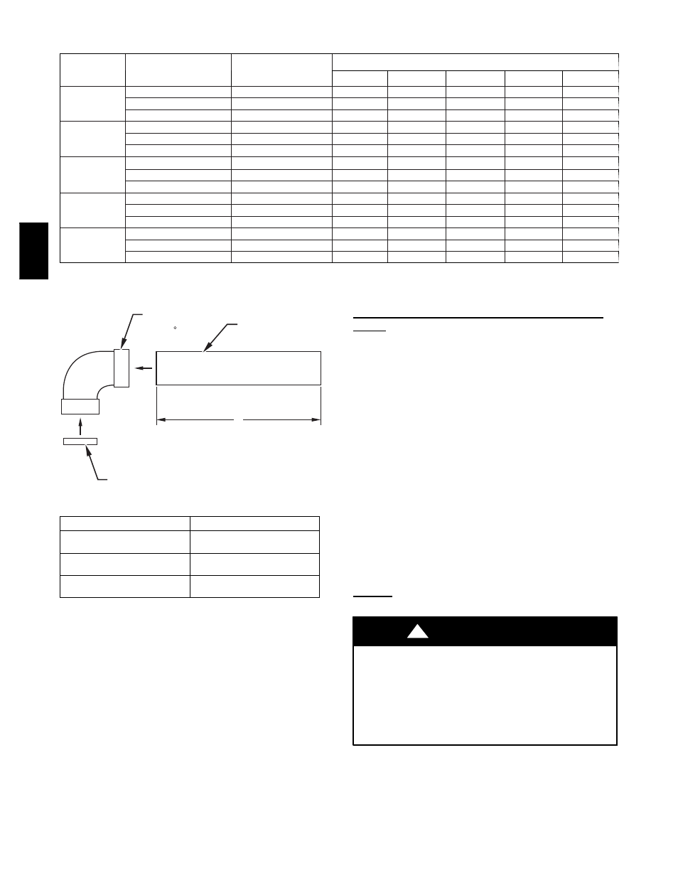
FIELD-SUPPLIED
2-IN. (51 mm) DIA.
PVC PIPE
FIELD-SUPPLIED
2-IN. (51 mm) DIA.
PVC 90 ELBOW
COMBUSTION-AIR DISC LOCATION-NON DIRECT
VENT/1-PIPE SYSTEM (FACTORY-SUPPLIED IN
LOOSE PARTS BAG)
A
A05122
CASING WIDTH
A
17---1/2 (445)
8---1/2 +/--- ½
(216 +/--- 13)
21 (533)
10---1/2 +/--- ½
(267 +/--- 13)
24---1/2 (622)
12 +/--- ½
(305 +/--- 13)
Fig. 39 -- Combustion--Air Inlet Pipe Assembly --
In. (mm)
4. Insert assembled combustion air inlet pipe into intake
housing as shown in Fig. 38.
5. Drill a 1/8--in. hole in 2--in, combustion air pipe using the
hole in intake housing as a guide.
6. Install a field--supplied No. 6 or No. 8 sheet metal screw
into combustion air pipe.
7. Install casing hole filler cap (factory--supplied in loose parts
bag) in unused combustion air pipe casing hole.
NOTE: Do not attach combustion air intake pipe permanently to
combustion air intake housing since it may be necessary to remove
pipe for service of igniter or flame sensor.
Attachment of Combustion Air Intake Housing Plug
Fitting
The combustion--air intake plug fitting must be installed in unused
combustion air intake housing. This fitting must be attached by
using RTV sealant, or by drilling a 1/8--in. (3 mm) hole in fitting,
using hole in intake housing as a guide. Install a field--supplied No.
6 or No. 8 sheet metal screw.
NOTE: DO NOT OVERTIGHTEN SCREW. Breakage of intake
housing or fitting may cause air leakage to occur.
A plugged drain connection has been provided on this fitting for
use when moisture is found in combustion air intake pipe and
combustion box. If use of this drain connection is desired, drill out
fitting’s tap plug with 3/16--in. drill and connect a field--supplied
3/8--in. tube. This tube should be routed to open condensate drain
for furnace and A/C (if used), and should be trapped, as shown in
Fig. 41.
NOTE:
(Direct Vent/2--Pipe System ONLY). Moisture in
combustion air intake may be a result of improper termination.
Ensure combustion air pipe termination is similar to those as
shown in Fig. 43 so that it will not be susceptible to area where
light snow or others sources of moisture could be pulled in.
VENT PIPE
General
Furnace vent connection must be attached as shown in Fig. 38.
CARBON MONOXIDE POISONING AND PROPERTY
DAMAGE HAZARD
Failure to follow this warning could result in property damage,
personal injury, or death.
Vent pipes must be airtight. NOTE: A 2--in. (51 mm) diameter
pipe must be used within the furnace casing. Make all pipe
diameter transitions outside furnace casing per Fig. 40.
!
WARNING
NOTE: A 2--in. (51 mm) diameter pipe must be used within the
furnace casing. Make all pipe diameter transitions outside furnace
casing per Fig. 40.
355A