Step 11 — condensate drain – Bryant Bruant 4 Way Gas 355AAV User Manual
Page 41
41
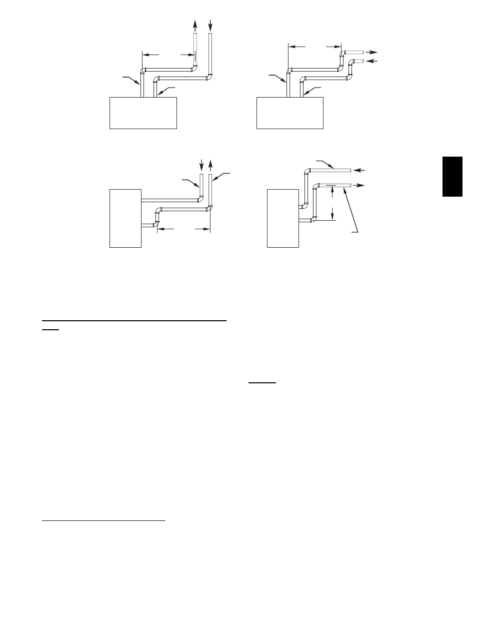
HORIZONTAL TO ROOF
HORIZONTAL TO SIDEWALL
VERTICAL TO SIDEWALL
VERTICAL TO ROOF
VENT PIPE
COMBUSTION-AIR PIPE
COMBUSTION-AIR PIPE
VENT PIPE
COMBUSTION-AIR PIPE
VENT PIPE
COMBUSTION-AIR PIPE
VENT PIPE
12
″ MIN
12
″ MIN
12
″ MIN
(304.8mm)
12
″ MIN
(304.8mm)
NOTE: A 12-in. (304.8mm) minimum offset pipe section is recommended
with short (5 to 8 ft / 1.5 to 2.5M) vent systems. This recommendation
is to reduce excessive condensate droplets.
(305mm)
(305mm)
A96230
Fig. 42 -- Short Vent (5 to 8 Ft. or 1.5M -- 2.4M) System
Two--Pipe Termination Kit (Direct Vent/2--Pipe System
Only
Determine an appropriate location for termination kit using the
guidelines provided in section “Vent Termination: General” in this
instruction.
1. Cut 2 holes, 1 for each pipe, of appropriate size for pipe size
being used.
2. Loosely install elbow in bracket and place assembly on
combustion--air pipe.
Roof terminations--Loosely install pipe coupling on prop-
erly cut vent pipe. Coupling must be positioned so bracket
will mount as shown in Fig. 43.
For applications using combustion--air pipe option, indic-
ated by dashed lines in Fig. 43, install 90_ street elbow into
90_ elbow, making a U--fitting. A 180_ U--fitting may be
used.
Sidewall terminations--Install bracket as shown in Fig. 43.
For applications using vent pipe option indicated by dashed
lines in Fig. 43, rotate vent elbow 90_ from position shown
in Fig. 43.
3. Disassemble loose pipe fittings. Clean and cement using
same procedures as used for system piping.
4. Check required dimensions as shown in Fig. 43.
Multiventing and Vent Terminations
When 2 or more 355AAV Furnaces are vented near each other,
each furnace must be individually vented. NEVER common vent
or breach vent 355AAV furnaces.
(Direct Vent/2--Pipe System ONLY)--When 2 or more 355AAV
furnaces are vented near each other, 2 vent terminations may be
installed as shown in Fig. 43, but next vent termination must be at
least 36 in. (914 mm) away from first 2 terminations. It is
important that vent terminations be made as shown in Fig. 43 to
avoid recirculation of flue gases.
Step 11 — Condensate Drain
General
Condensate trap is shipped installed in the blower shelf and factory
connected for UPFLOW applications. Condensate trap must be
RELOCATED for use in DOWNFLOW and HORIZONTAL
applications.
Condensate trap MUST be used for all applications.
An external trap is not required when connecting the field drain to
this condensate trap.
The field drain connection (condensate trap or drain tube coupling)
is sized for 1/2--in. (13 mm) CPVC, 1/2--in. PVC (13 mm), or
5/8--in. (16 mm) ID tube connection.
Drain pipe and fittings must conform to ANSI standards and
ASTM D1785, D2466, or D2846. CPVC or PVC cement must
conform to ASTM D2564 or F493. Primer must conform to
ASTM F656. In Canada, use CSA or ULC certified schedule 40
CPVC or PVC drain pipe, fittings, and cement.
When a condensate pump is required, select a pump which is
approved for condensing furnace applications. To avoid
condensate spillage, select a pump with an overflow switch.
355A