Caution, Combustion air pipe – Bryant Bruant 4 Way Gas 355AAV User Manual
Page 31
31
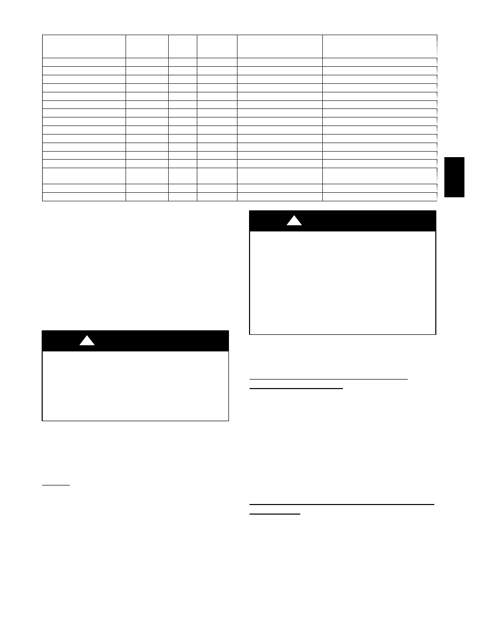
Table 7 – Approved Combustion--Air and Vent Pipe, Fitting and Cement Materials
ASTM SPECIFICATION
(MARKED ON
MATERIAL)
MATERIAL
PIPE
FITTINGS
SOLVENT CEMENT AND
PRIMERS
DESCRIPTION
D1527
ABS
Pipe
—
—
Schedule—40
D1785
PVC
Pipe
—
—
Schedule—40
D2235
For ABS
—
—
Solvent Cement
For ABS
D2241
PVC
Pipe
—
—
SDR—21 & SDR—26
D2466
PVC
—
Fittings
—
Schedule—40
D2468
ABS
—
Fittings
—
Schedule—40
D2564
For PVC
—
—
Solvent Cement
For PVC
D2661
ABS
Pipe
Fittings
—
DWV at Schedule—40 IPS sizes
D2665
PVC
Pipe
Fittings
—
DWV
F438
CPVC
—
Fittings
—
Schedule—40
F441
CPVC
Pipe
—
—
Schedule—40
F442
CPVC
Pipe
—
—
SDR
F493
For CPVC
—
—
Solvent Cement
For CPVC
F628
ABS
Pipe
—
—
Cellular Core DWV at Schedule---40
IPS sizes
F656
For PVC
—
—
Primer
For PVC
F891
PVC
Pipe
—
—
Cellular Core Schedule---40 & DWV
An abandoned masonry chimney may be used as a raceway for
properly
insulated
and
supported
combustion--air (when
applicable) and vent pipes. Each furnace must have its own set of
combustion--air and vent pipes and be terminated individually, as
shown in Fig. 43 for Direct Vent (2--Pipe) system and Fig. 44 for
Non--Direct Vent (1--Pipe) system.
A furnace shall not be connected to a chimney flue serving a
separate appliance designed to burn solid fuel.
Other gas appliances with their own venting system may also use
the abandoned chimney as a raceway providing it is permitted by
local code, the current edition of the National Fuel Gas Code and
the vent or liner manufacturer’s installation instructions. Care must
be taken to prevent the exhaust gases from one appliance from
contaminating the combustion air of other gas appliances.
UNIT MAY NOT OPERATE
Failure to follow this caution may result in intermittent unit
operation.
When vent pipe is exposed to temperatures below freezing,
such as when it passes through an unheated space or when a
chimney is used as a raceway, pipe must be insulated as shown
in Table 10 with Armaflex--type insulation.
CAUTION
!
Furnace combustion air and vent pipe connections are sized for
2--in. (51 mm) pipe. Any pipe size change should be made outside
furnace casing in vertical pipe. The transition has to be made as
close to the furnace as reasonably possible. See Fig. 40.
COMBUSTION AIR PIPE
General
Furnace combustion--air connection must be attached as shown in
Fig. 38. Combustion--air intake housing plug may need to be
relocated in some applications.
For Non--Direct Vent (1--Pipe) system, combustion--air must
terminate outside of furnace casing with 1 elbow. Orient elbow so
that its opening faces down for upflow or downflow applications.
Orient elbow so that its opening faces sideways (left or right) for
horizontal left or horizontal right applications (See Fig. 38.)
Maintain a 3--in minimum clearance between the opening of the
combustion--air inlet pipe and any object.
UNIT CORROSION HAZARD
Excessive exposure to contaminated combustion air may result
in safety and performance related problems.
Combustion air must not be taken from inside structure
because inside air is frequently contaminated by halogens,
which include fluorides, chlorides, bromides, and iodides.
These elements are found in aerosols, detergents, bleaches,
cleaning solvents, salts, air fresheners, adhesives, paint, and
other household products. Locate combustion--air inlet as far
as possible from swimming pool and swimming pool pump
house. pipe.
CAUTION
!
NOTE: All pipe joints must have cemented attachment of
combustion--air inlet pipe to inlet housing connection, since it may
be necessary to remove pipe for servicing.
Assembly of Combustion Air Pipe (Non--Direct
Vent/1--Pipe System ONLY)
1. Permanently install perforated disk assembly (factory sup-
plied in loose parts bag) in combustion--air elbow using
RTV or by cementing, as shown in Fig. 39. For 120,000
Btuh size units only: separate the 2 halves of perforated disk
assembly and use only the shouldered disk half.
2. Determine the length of straight portion of combustion--air
inlet pipe from Fig. 39.
3. Cut field--supplied 2--in. (51 mm) diameter PVC pipe to
length as determined per Fig. 39.
4. Permanently attach elbow/perforated disk assembly to
straight portion of pipe using RTV or by cementing as
shown in Fig. 39.
Assembly of Combustion Air Pipe (Direct Vent--2--Pipe
System ONLY)
1. Using Table 11, individually determine the smallest
combustion air and vent pipe diameters permitted for each
pipe. Pick the larger of these two pipe diameters and use this
for both combustion--air and vent pipes.
NOTE: Do not count elbows or pipe sections in terminations or
within furnace (All elbows shown in Fig. 43 are not to be counted).
355A