Bryant Bruant 4 Way Gas 355AAV User Manual
Page 13
13
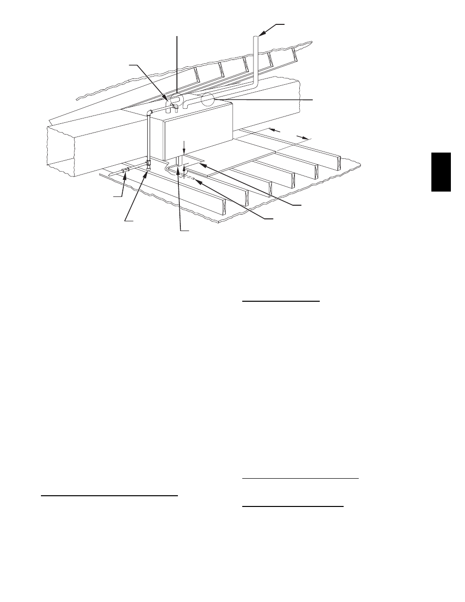
VENT
MANUAL
SHUTOFF
GAS VALVE
SEDIMENT
TRAP
CONDENSATE
TRAP
DRAIN
ACCESS OPENING
FOR TRAP
30-IN. (762mm) MIN
WORK AREA
A 12-IN. (305mm) MIN HORIZONTAL PIPE
SECTION IS RECOMMENDED WITH
SHORT (5 TO 8 FT / 1.5 TO 2.4M) VENT
SYSTEMS TO REDUCE EXCESSIVE
CONDENSATE DROPLETS FROM
EXITING THE VENT PIPE.
A 3-IN.(76mm) MINIMUM CLEARANCE
TO COMBUSTION-AIR INTAKE
IS REQUIRED.
5
3
/
4
IN. (146mm)
NOTE: LOCAL CODES MAY REQUIRE A DRAIN PAN UNDER THE
FURNACE AND CONDENSATE TRAP WHEN A CONDENSING
FURNACE IS INSTALLED ABOVE FINISHED CEILINGS.
COMBUSTION AIR
INTAKE
A96184
Fig. 13 -- Attic Location and Working Platform for Non--Direct Vent (1--Pipe) Applications -- Sizes 040 through 120 Only
c. Route extended tube (blue label) to condensate trap and
cut to appropriate length.
d. Clamp tube to prevent any condensate leakage.
2. Inducer Housing Drain Tube
a. Remove and discard LOWER (molded) inducer housing
drain tube which was previously connected to
condensate trap.
b. Use inducer housing drain extension tube (violet label
and factory--supplied in loose parts bag) to connect
LOWER inducer housing drain connection to
condensate trap.
c. Determine appropriate length, cut, and connect tube.
d. Clamp tube to prevent any condensate leakage.
3. Relief Port Tube
a. Extend collector box tube (green label) which was
previously connected to condensate trap by splicing to
small diameter tube (factory--supplied in loose parts
bag).
b. Route extended collector box pressure tube to relief port
connection on condensate trap.
c. Determine appropriate length, cut, and connect tube.
d. Clamp tube to prevent any condensate leakage.
Condensate Trap Field Drain Attachment
Refer to Condensate Drain section for recommendations and
procedures.
Pressure Switch Tubing
The LOWER collector box pressure tube (pink label) is factory
connected to the High Pressure Switch for use when furnace is
installed in UPFLOW applications. This tube MUST be
disconnected, extended, rerouted, and then reconnected to the
pressure switch in HORIZONTAL LEFT applications for 060 and
080 heating input furnaces.
NOTE: See Fig. 11 or tube routing label on main furnace door to
check for proper connections.
Modify tube as described below.
1. Disconnect collector box pressure tube (pink label) attached
to High Pressure Switch.
2. Use smaller diameter tube (factory--supplied in loose parts
bag) to extend tube disconnected in item 1.
3. Route extended tube:
a. Behind inducer housing.
b. Between blower shelf and inducer housing.
4. Determine appropriate length, cut, and reconnect tube to
High Pressure Switch connection labeled COLLECTOR
BOX.
Condensate Trap Freeze Protection
Refer to Condensate Drain Protection section for recommendations
and procedures.
Construct a Working Platform
Construct working platform where all required furnace clearances
are met. (See Fig. 3 and 12 or 13.)
355A