Caution – Bryant Bruant 4 Way Gas 355AAV User Manual
Page 29
29
FACTORY
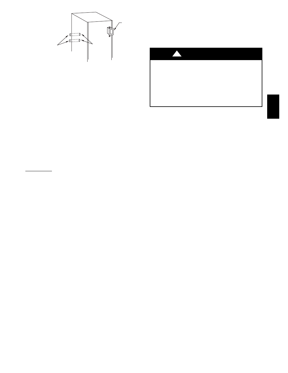
INSTALLED
LOCATION
UNUSED 7/8-IN. (22 mm)
DIAMETER POWER
ENTRY HOLES
POWER ENTRY HOLE
FILLER PLUG (FACTORY-
SUPPLIED LOOSE PARTS BAG)
A05113
Fig. 34 -- Factory Installed J-Box Location
SETUP SWITCHES (SW1)
The furnace control has 8 setup switches that may be set to meet
the application requirements. Position these setup switches for the
appropriate requirement.
1. Remove main furnace door and blower access panel.
2. Locate setup switches on furnace control. (See Fig. 37.)
3. See Table 13 for setup switch description.
4. Replace main furnace door and blower access panel.
NOTE: If a bypass humidifier is used, setup switch SW1--3 (Low
HEAT Rise Adjust) should be in ON position. This compensates
for the increased temperature in return air resulting from bypass.
NOTE:
If modulating dampers are used, blower motor
automatically compensates for modulating dampers. If manual
disconnect switch is to be mounted on furnace, select a location
where a drill or fastener will not contact electrical or gas
components.
24--V Wiring
Make field 24--v thermostat connections at 24--v terminal block on
furnace control. Y wire from thermostat MUST be connected to
Y/Y2 terminal on control, as shown in Fig. 32, for proper cooling
operation. The 24--v terminal block is marked for easy connection
of field wiring. (See Fig. 37.) The 24--v circuit contains a 3--amp,
automotive--type fuse located on furnace control. (See Fig. 37.)
Any electrical shorts of 24--v wiring during installation, service, or
maintenance may cause fuse to blow. If fuse replacement is
required, use only a fuse of identical size (3 amp) and type. The
furnace control will flash status code 24 when fuse needs
replacement.
NOTE: Use AWG No. 18 color--coded copper thermostat wire for
lengths up to 100 ft. (30 M). For wire lengths over 100 ft. (30 M),
use AWG No. 16 wire.
NOTE: For additional thermostat connection diagrams, reference
Fig. 51--58.
ACCESSORIES
1. Electronic Air Cleaner (EAC)
The furnace control EAC terminals are energized with 115v
(1.0--amp maximum) during blower operation.
Connect an accessory Electronic Air Cleaner (if used) using
1/4--in. (6 mm) female quick connect terminals to the two
male 1/4--in. (6 mm) quick--connect terminals on the control
board marked EAC--1 and EAC--2. The terminals are rated
for 115VAC, 1.0 amps maximum and are energized during
blower motor operation. (See Fig. 37.)
2. Humidifier (HUM)
Connect an accessory 24 VAC, 0.5 amp maximum
humidifier (if used) to the 1/4--in. (6 mm) male
quick--connect HUM terminal and COM--24V screw
terminal on the control board thermostat strip. The HUM
terminal is energized when blower is energized in heating.
(See Fig. 37.)
UNIT DAMAGE HAZARD
Failure to follow this caution may result in unit component
damage.
DO NOT connect furnace control HUM terminal to HUM
(humidifier) terminal on Thermidistatt, Zone Controller or
similar device. See Thermidistatt, Zone Controller,
thermostat, or controller manufacturer’s instructions for proper
connection.
CAUTION
!
Step 9 — Removal of Existing Furnaces from
Common Vent Systems
When an existing Category I furnace is removed or replaced, the
original venting system may no longer be sized to properly vent
the remaining attached appliances. An improperly sized Category I
venting system could cause the formation of condensate in the
furnace and vent, leakage of condensate and combustion products,
spillage of combustion products into the living space, etc.
Step 10 — Combustion Air and Vent Pipe Systems
GENERAL
For additional venting information, contact www.Bryant.com.
Vent system or vent connectors may need to be resized. For any
other appliances when resizing vent systems or vent connectors,
system or connector must be sized to approach minimum size as
determined using appropriate table found in the NFGC
NFPA54/ANSI Z223.1--2006 or CAN/CSA--B149.1--05.
The 355AAV can be vented as either a direct vent or as a
non--direct vent application. A direct vent system shall be installed
in accordance with the direct vent (2--pipe) procedures in the
following Combustion Air and Vent Pipe Systems section. For
non--direct vent (1--pipe) applications, refer to the non--direct vent
(1--pipe) procedures in the same section.
Common venting prohibited.
DIRECT VENT/2--PIPE SYSTEM (ALL SIZES)
In a direct--vent (2--pipe) system, all air for combustion is taken
directly from outdoor atmosphere, and all flue products are
discharged to outdoor atmosphere. A factory accessory vent
termination kit MUST be used in a direct vent (2--pipe) system.
NON--DIRECT VENT/1--PIPE SYSTEM (SIZES
040 THROUGH 120 ONLY)
In a non--direct vent (1--pipe) system, all air for combustion is
taken from the area adjacent to furnace, and all flue products are
discharged to outdoor atmosphere. A factory--supplied perforated
disk assembly (in loose parts bag) MUST be used in combustion
air pipe elbow.
355A