Warning, Start--up, adjustments and safety check, Application – Bryant Bruant 4 Way Gas 355AAV User Manual
Page 43: Condensate drain protection, Step 1 — general
43
Table 12 – Vent Termination Kit for Direct Vent / 2--Pipe System
DIRECT VENT (2 PIPE) TERMINATION KIT
TERMINATION SYSTEM
DIAMETER OF COMBUSTION AIR AND
VENT PIPES --- IN. (MM)
2---in. (51 mm) Concentric Vent Kit
Single Penetration of Wall or Roof
1, 1---1/2, 2, or 2---1/2
(25, 38, 51, or 64)
3---in. (76 mm) Concentric Vent Kit
Single Penetration of Wall or Roof
2---1/2, 3 or 4 (64, 76, or 102)
2---in. (51 mm)Termination Bracket Kit
2Pipe Termination System
1, 1---1/2 or 2 (25, 38, or 51)
3---in. (76 mm) Termination Bracket Kit
2Pipe Termination System
2---1/2, 3 or 4 (64, 76, or 102)
Furnace condensate is mildly acidic, typically in the pH range of
3.2 to 4.5. Due to corrosive nature of this condensate, a condensate
pH neutralizing filter may be desired. Check with local authorities
to determine if a pH neutralizer is required.
APPLICATION
The furnace, A/C, and humidifier drains may be combined and
drained together. The A/C drain must have an external,
fieldsupplied trap prior to the furnace drain connection. All drain
connections (furnace, A/C, or humidifier) must be terminated into
an open or vented drain as close to the respective equipment as
possible to prevent siphoning of the equipment’s drain.
See Fig. 45 for example of possible field drain attachment using
1/2--in. (13 mm) CPVC or PVC tee for vent and A/C or humidifier
drain connection.
Outdoor draining of the furnace is permissible if allowed by local
codes. Caution should be taken when freezing ambient may freeze
drain pipe and prohibit draining.
PERSONAL INJURY HAZARD
Failure to follow this warning could result in property damage
and personal injury or death.
Caution should be taken to prevent draining causing slippery
conditions . Excessive condensate draining may cause
saturated soil conditions which may result in damage to plants.
!
WARNING
CONDENSATE DRAIN PROTECTION
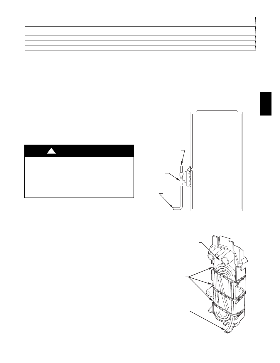
Freezing condensate left in condensate trap and drain line may
cause cracks, and possible water damage may occur. If freeze
protection is required, use condensate freeze protection accessory
or equivalent 3 to 6 watt per ft. at 120v and 40_F (4_C)
self--regulating, shielded, and waterproof heat tape. See Installation
Instructions supplied with accessory or heat tape manufacturer’s
recommendations.
1. Fold heat tape in half and wrap on itself 3 times.
2. Locate heat tape between sides of condensate trap back.
(See Fig. 46.)
3. Use wire ties to secure heat tape in place. Wire ties can be
positioned in notches of condensate trap sides. (See Fig.
46.)
4. Wrap field drain pipe with remaining heat tape,
approximately 1 wrap per ft.
5. When using field--supplied heat tape, follow heat tape
manufacturer’s instructions for all other installation
guidelines.
START--UP, ADJUSTMENTS AND SAFETY
CHECK
Step 1 — General
1. Furnace must have a 115--v power supply properly
connected and grounded.
NOTE: Proper polarity must be maintained for 115--v wiring. If
polarity is incorrect, control status indicator light flashes rapidly
and furnace does not operate.
2. Thermostat wire connections at terminals R, W/W1, G, and
Y/Y2 must be made at 24--v terminal block on furnace
control.
3. Natural gas service pressure must not exceed 0.5 psig
(14--in. wc), but must be no less than 0.16 psig (4.5--in. wc).
4. Blower access panel must be in place to complete 115--v
electrical circuit to furnace.
OPEN STAND
PIPE FOR
A/C OR
HUMIDIFIER
DRAIN
TEE
TO OPEN
DRAIN
A94054
Fig. 45 -- Example of Field Drain Attachment
CONDENSATE TRAP
WIRE TIE(S)
HEAT TAPE
(3 WRAPS MINIMUM)
A93036
Fig. 46 -- Condensate Trap Heat Tape
355A