Warning, Continuous fan (cf) setup switches – Bryant Bruant 4 Way Gas 355AAV User Manual
Page 28
28
Table 6 – Electrical Data
UNIT SIZE
VOLTS---
HERTZ---
PHASE
OPERATING VOLTAGE
RANGE
MAXIMUM
UNIT
AMPS
MINIMUM
WIRE SIZE
MAXIMUM
WIRE LENGTH
FT. (M)}
MAXIMUM FUSE
OR CKT BKR
AMPS**
Maximum*
Minimum*
040---14 / 042040
115---60---1
127
104
8.90
14
31 (9)
15
060---14 / 042060
115---60---1
127
104
8.90
14
31 (9)
15
080---14 / 042080
115---60---1
127
104
8.90
14
30 (9)
15
080---20 / 060080
115---60---1
127
104
14.00
12
31 (9)
20
100---20 / 060100
115---60---1
127
104
14.00
12
31 (9)
20
120---20 / 060120
115---60---1
127
104
14.00
12
31 (9)
20
* Permissible limits of voltage range at which unit will operate satisfactorily.
{
Unit ampacity = 125 percent of largest operating component’s full load amps plus 100 percent of all other potential operating components’ (EAC, humidifier,
etc.) full load amps.
}
Length shown is as measured 1 way along wire path between unit and service panel for maximum 2 percent voltage drop.
** Time---delay type is recommended.
by power supply is sufficient to handle load imposed by this
equipment. Refer to rating plate or Table 6 for equipment electrical
specifications.
Make all electrical connections in accordance with National
Electrical Code (NEC) ANSI/NFPA 70--2008 and any local codes
or ordinances that might apply. For Canadian installations, all
electrical connections must be made in accordance with Canadian
Electrical Code CSA C22.1 or authorities having jurisdiction.
Field--supplied wiring shall conform with the limitations of 63_F
(33_C) rise.
The furnace must be electrically grounded in accordance with local
codes; or in the absence of local codes, with the National Electric
Code ANSI/NFPA 70 and/or the Canadian Electric Code, CSA
C22.1, Part I, if an external electrical source is utilized.
Use a separate branch electrical circuit containing a properly sized
fuse or circuit breaker for this furnace. See Table 6 for wire size
and fuse specifications. A disconnecting means must be located
within sight from and readily accessible to furnace.
NOTE: Proper polarity must be maintained for 115--v wiring. If
polarity is incorrect, furnace control status code indicator light will
flash rapidly and furnace will NOT operate.
FIRE HAZARD
Failure to follow this warning could result in intermittent
operation or performance satisfaction.
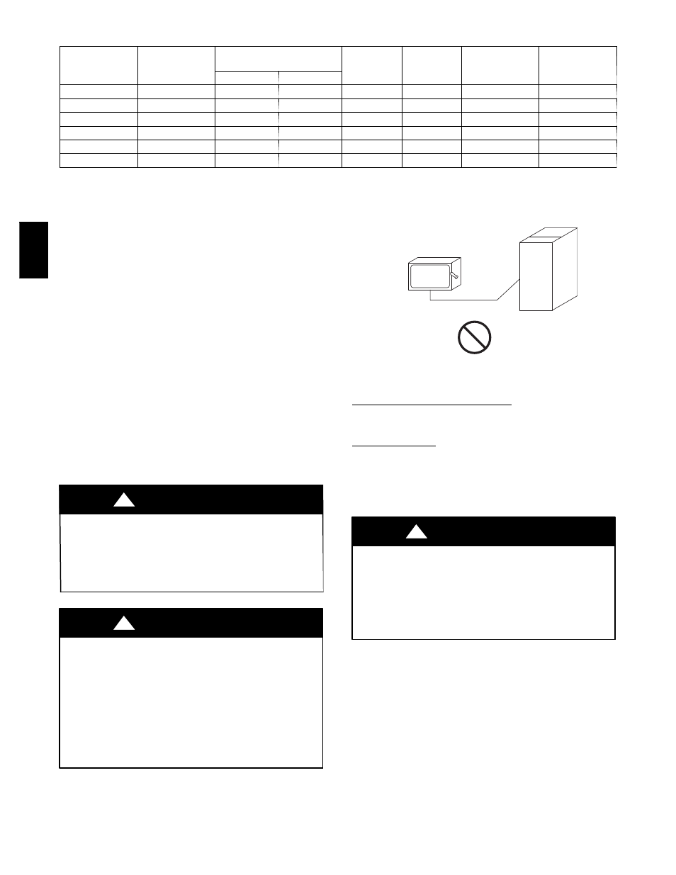
Do not connect aluminum wire between disconnect switch and
furnace. Use only copper wire. (See Fig. 33.)
!
WARNING
ELECTRICAL AND FIRE HAZARD
Failure to follow this warning could result in electrical shock,
fire or death.
The cabinet MUST have an uninterrupted or unbroken ground
according to NEC ANSI/NFPA 70--2008 and Canadian
Electrical Code CSA C22.1 or local codes to minimize
personal injury if an electrical fault should occur. This may
consist of electrical wire or conduit approved for electrical
ground when installed in accordance with existing electrical
codes. Do not use gas piping as an electrical ground.
!
WARNING
COPPER
WIRE ONLY
ELECTRIC
DISCONNECT
SWITCH
ALUMINUM
WIRE
A93033
Fig. 33 -- Disconnect Switch and Furnace
Factory Installed J--Box Location
Install power entry hole filler plugs (factory--supplied in loose parts
bag) in unused power entry holes. (See Fig. 34.)
J--Box Relocation
1. Remove 2 screws holding auxiliary J--box. (See Fig. 35.)
2. Rotate J--box 180_ and attach box to left side, using holes
provided.
3. Install power entry hole filler plugs (factory--supplied loose
parts bag) in unused power entry holes. (See Fig. 35.)
FIRE OR ELECTRICAL SHOCK HAZARD
Failure to follow this warning could result in intermittent unit
operation or performance satisfaction.
If manual disconnect switch is to be mounted on furnace,
select a location where a drill or fastener will not contact
electrical or gas components.
!
WARNING
CONTINUOUS FAN (CF) SETUP SWITCHES
The CF setup switches are used to select desired airflow when
thermostat is in continuous fan mode or to select low--cooling
airflow for two--speed cooling units. This setup feature allows
continuous fan airflow or low--cooling airflow to be adjusted. To
set desired continuous fan airflow or low--cooling airflow:
1. Remove main furnace door and blower access panel.
2. Locate CF setup switches on furnace control. (See Fig. 37.)
3. Determine desired continuous fan airflow or low--cooling
airflow.
4. Use Fig. 47 or wiring schematic to determine proper setup
position of CF switches. (See Fig. 36.)
5. Replace main furnace door and blower access panel.
355A