Caution, Warning – Bryant Bruant 4 Way Gas 355AAV User Manual
Page 12
12
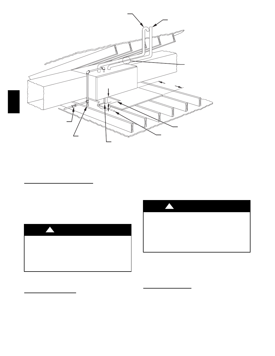
COMBUSTION - AIR
INTAKE
VENT
MANUAL
SHUTOFF
GAS VALVE
SEDIMENT
TRAP
CONDENSATE
TRAP
DRAIN
ACCESS OPENING
FOR TRAP
30
″
(762 mm)MIN
WORK AREA
A 12-IN. (305 mm) MIN HORIZONTAL PIPE
SECTION IS RECOMMENDED WITH
SHORT (5 TO 8 FT / 1.5 TO 2.4 M) VENT
SYSTEMS TO REDUCE EXCESSIVE
CONDENSATE DROPLETS FROM
EXITING THE VENT PIPE.
5
3
/
4
″
(146 mm)
NOTE: LOCAL CODES MAY REQUIRE A DRAIN PAN UNDER THE
FURNACE AND CONDENSATE TRAP WHEN A CONDENSING
FURNACE IS INSTALLED ABOVE FINISHED CEILINGS.
A93031
Fig. 12 -- Attic Location and Working Platform for Direct Vent (2--Pipe) Application -- All Sizes
Condensate Trap Freeze Protection
Refer to Condensate Drain Protection section for recommendations
and procedures.
Step 4 — Horizontal Left (Supply--Air Discharge)
Applications
A horizontal left furnace application is where furnace blower is
located to the right of combustion and controls section of furnace,
and conditioned air is discharged to the left.
MINOR PROPERTY HAZARD
Failure to follow this caution may result in minor property
damage.
Local codes may require a drain pan under entire furnace and
condensate trap when a condensing furnace is used in an attic
application or over a finished ceiling.
CAUTION
!
NOTE: In Canada, installations shall be in accordance with
current NSCNGPIC and/or local codes.
Condensate Trap Location
The condensate trap must be removed from the factory--installed
blower shelf location and relocated in selected application location
as shown in Fig. 2 or 11.
To relocate condensate trap from the blower shelf to desired
location, perform the following:
1. Remove 3 tubes connected to condensate trap.
2. Remove trap from blower shelf by gently pushing tabs
inward and rotating trap.
3. Remove casing hole filler cap from casing hole. (See Fig. 2
or 11.)
4. Install casing hole filler cap (factory--supplied in loose parts
bag) into blower shelf hole where trap was removed.
CARBON MONOXIDE POISONING HAZARD
Failure to follow this warning could result in personal injury
or death.
Casing hole filler cap must be installed in blower shelf hole
when condensate trap is relocated to prevent combustion
products being drawn in from appliances in the equipment
room.
!
WARNING
5. Install condensate trap into left--hand side casing hole by
inserting tube connection stubs through casing hole and
rotating until tabs snap into locking position.
6. Fill unused condensate trap casing holes with plastic filler
caps (factory--supplied in loose parts bag).
Condensate Trap Tubing
NOTE: See Fig. 11 or tube routing label on main furnace door to
check for proper connections.
1. Collector Box Drain Tube
a. Install drain tube coupling (factory--supplied in loose
parts bag) into collector box drain tube (blue label)
which was previously connected to condensate trap.
b. Connect large diameter drain tube and clamp
(factorysupplied in loose parts bag) to drain tube
coupling, extending collector box drain tube.
355A