Warning, Caution, Step 8 — electrical connections – Bryant Bruant 4 Way Gas 355AAV User Manual
Page 26: 355a
26
Table 5 –
Maximum Capacity of Pipe*
NOMINAL
IRON
PIPE SIZE
IN. (MM)
INTERNAL
DIA.
IN. (MM)
LENGTH OF PIPE --- FT. (M)
10
(3.0)
20
(6.0)
30
(9.1)
40
(12.1)
50
(15.2)
1/2 (13)
0.622
(158)
175
120
97
82
73
3/4 (19)
0.824 (21)
360
250
200
170
151
1 (25)
1.049 (27)
680
465
375
320
285
1-1/4 (32)
1.380 (35)
1400
950
770
660
580
1-1/2 (38)
1.610 (41)
2100
1460
1180
990
900
* Cubic ft. of gas per hr for gas pressures of 0.5 psig (14--- in. wc) or less and
a pressure drop of 0.5--- in wc (based on a 0.60 specific gravity gas). Ref:
Table 9.2 NFGC.
Piping should be pressure and leak tested in accordance with
NFGC in the United States or NSCNGPIC in Canada, local, and
national plumbing and gas codes before the furnace has been
connected. If pressure exceeds 0.5 psig (14--in. wc), gas supply
pipe must be disconnected from furnace and capped before
pressure test.
If test pressure is equal to or less than 0.5 psig (14--in. wc), turn off
electric shutoff switch located on gas valve before test. It is
recommended that ground joint union be loosened before pressure
testing. After all connections have been made, purge lines and
check for leakage at furnace prior to placing it into service.
The gas supply pressure shall be within the maximum (13.6--in.
wc) and and minimum (4.5--in. wc) inlet supply pressures marked
on the rating plate with the furnace burners ON at HI--HEAT and
OFF.
BOTTOM
CLOSURE
PANEL
FRONT FILLER
PANEL
A93047
Fig. 29 -- Removing Bottom Closure Panel
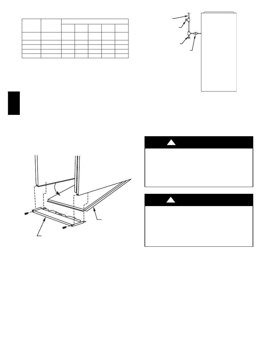
UNION
SEDIMENT
TRAP
MANUAL
SHUTOFF
VALVE
(REQUIRED)
GAS
SUPPLY
A93324
Fig. 30 -- Typical Gas Pipe Arrangement
Step 8 — Electrical Connections
See Fig. 32 for field wiring diagram showing typical field 115--v
and 24--v wiring. Check all factory and field electrical connections
for tightness.
ELECTRICAL OPERATION HAZARD
Failure to follow this warning could result in personal injury
or death.
Blower access door switch opens 115--v power to furnace
control. No component operation can occur. Do not bypass or
close switch with panel removed.
!
WARNING
UNIT MAY NOT OPERATE
Failure to follow this caution may result in intermittent unit
operation.
Furnace control must be grounded for proper operation or
control will lock out. Control is grounded through
green/yellow wire connected to gas valve and burner box
screw.
CAUTION
!
115--V WIRING Before proceeding with electrical connections,
make certain that voltage, frequency, and phase correspond to that
specified on furnace rating plate. Also, check to be sure that service
provided
355A