Caution, Continuous fan (cf) setup switches, 355a – Bryant Bruant 4 Way Gas 355AAV User Manual
Page 44
44
AIR CONDITIONING
TONS (12,000 BTU/HR)
AIRFLOW* (CFM)
040,060 & 080---14
MODEL
080---20 & 100 MODEL
120 MODEL
1---1/2
525 (600)
X
2
700 (800)
X
X
X
2---1/2
875 (1000)
X
X
X
3
1050 (1200)
X
X
X
3---1/2
1225 (1400)
X
X
X
4
1400 (1600)
X
X
5
1750 (2000)
X
X
6
2100 (2100)
X
X Indicates an allowable selection.
* Airflow shown in parentheses is airflow unit that the unit will deliver when setup switch SW1---5 is ON (selects 400 CFM/ton)
525
2
700
2
700
875
1050
875
700
875
2
1050
1050
1
1225
1225
1225
1400
1400
1225
1750
1
1750
1
1225
1750
2100
DEF.
DEF.
DEF.
5T080, 100
120
BASED ON 350 CFM/TON (SETUP SWITCH SW1-5 OFF)
SETUP SWITCH SW2 & SW3 POSITIONS
MODEL
SIZE
600
2
800
2
800
1000
1200
1000
800
1000
2
1200
1200
1
1400
1400
1400
1600
1600
1400
2000
1
2000
1
1400
2000
2100
DEF.
DEF.
DEF.
040, 060, 3.5T080
5T080, 100
120
BASED ON 400 CFM/TON (SETUP SWITCH SW1-5 ON)
1. DEFAULT A/C AIRFLOW WHEN A/C SWITCHES ARE IN OFF POSITION
2. DEFAULT CONT. FAN AIRFLOW WHEN CF SWITCHES ARE IN OFF POSITION
3. SWITCH POSITIONS ARE ALSO SHOWN ON FURNACE WIRING DIAGRAM
SETUP SWITCH SW2 & SW3 POSITIONS
MODEL
SIZE
AIR CONDITIONING (A/C) OR CONTINUOUS-FAN (CF)
AIRFLOW SELECTION CHART
040, 060, 3.5T080
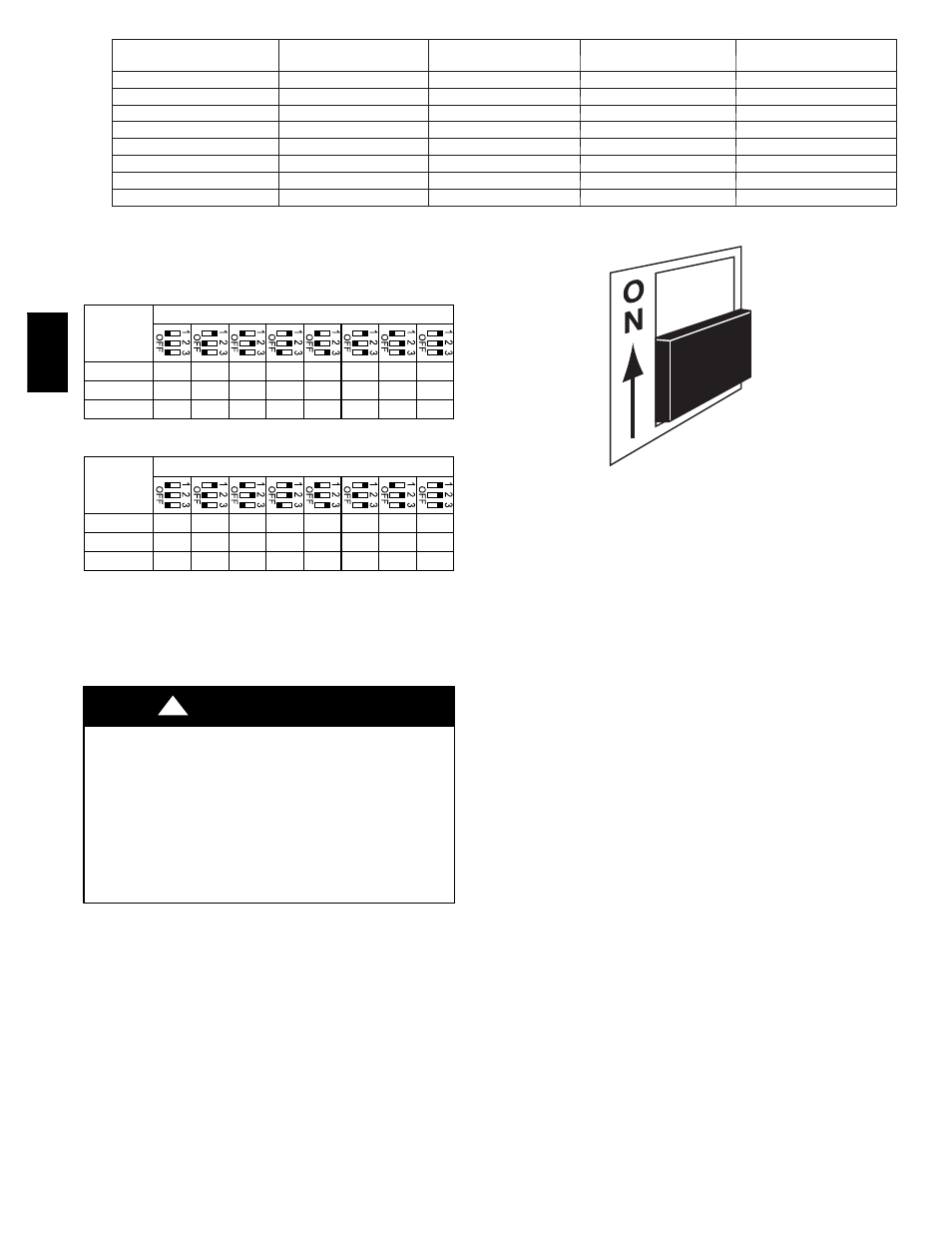
A07899
Fig. 47 -- A/C or CF Airflow Selection Chart Based on 350
and 400 CFM/Ton
UNIT MAY NOT OPERATE
Failure to follow this caution may result in intermittent unit
operation or performance satisfaction.
These furnaces are equipped with a manual reset limit switch
in burner box. This switch opens and shuts off power to the
gas valve if an overheat condition (flame rollout) occurs in
burner enclosure. Correct inadequate combustion--air supply
or improper venting condition before resetting switch. DO
NOT jumper this switch.
CAUTION
!
Before operating furnace, check flame rollout manual reset switch
for continuity. If necessary, press button to reset switch.
Step 2 — Select Setup Switch Positions
AIR CONDITIONING (A/C) SETUP SWITCHES
The air conditioning setup switches are used to match furnace
airflow to cooling unit used.
To set the desired cooling airflow:
1. Remove main furnace door and blower access panel.
A07907
Fig. 48 -- Example of Setup Switch in Off Position
2. Locate A/C setup switches on furnace control. (See Fig. 37.)
3. Determine air conditioning tonnage used.
4. Use Fig. 47 or wiring schematic to determine proper setup
position of A/C switches. (See Fig. 36 and 48.)
NOTE: Excessive airflow caused by improper A/C switch setup
may cause condensate blowoff in cooling mode.
5. Replace main furnace door and blower access panel.
NOTE: EAC--1 terminal is energized whenever blower operates.
HUM terminal is only energized when blower is energized in
heating.
CONTINUOUS FAN (CF) SETUP SWITCHES
The CF setup switches are used to select desired airflow when
thermostat is in continuous fan mode or to select low--cooling
airflow for two--speed cooling units. This setup feature allows
continuous fan airflow or low--cooling airflow to be adjusted. To
set desired continuous fan airflow or low--cooling airflow:
1. Remove main furnace door and blower access panel.
2. Locate CF setup switches on furnace control. (See Fig. 37.)
3. Determine desired continuous fan airflow or low--cooling
airflow.
4. Use Fig. 47 or wiring schematic to determine proper setup
position of CF switches. (See Fig. 36 and 48.)
5. Replace main furnace door and blower access panel.
355A