Buhler 2180 User Manual
Page 87
SECTION 2 - OPERATION
2-41
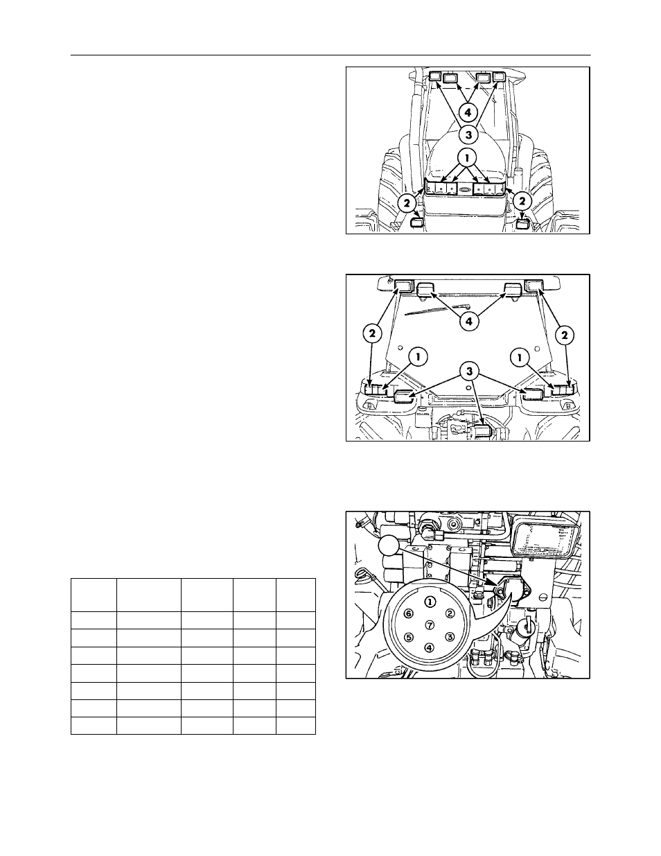
FRONT LIGHTS
The headlights, 1, are illuminated when the MASTER
LIGHT switch is in the headlight or work light position.
All four lights are illuminated when high beam is
selected. The outer headlights are illuminated when
low beam is selected.
The side and lower work lights, 2, are illuminated by
touching the work light selector switch, 1, with the
master switch in the work light position.
The directional signals/hazard lights, 3, are selected
with the hazard warning light switch or the
multi-function switch.
The optional upper front work lights, 4, are
illuminated by touching the work light selector switch,
4, with the master switch in the work light position.
64
REAR LIGHTS
The parking lights, 1, are illuminated with the light
switch in the park, headlight, or work light positions.
The brake lights, 1, are illuminated when both brake
pedals are depressed.
The rear directional/hazard lamps, 2, flash in unison
with the front directional/hazard lights.
The lower rear work lights, 3, are illuminated when
the master switch is in the work light position and
work light selector switch, 2, is selected. The center
work light may be turned off while leaving the outer
lamps illuminated. Use the toggle switch located on
the rear of the center lamp’s housing to turn off the
light.
The upper rear work lights, 4, are illuminated when
the master switch is in the work light position and
selector switch, 3, is selected.
65
SEVEN PIN AUXILIARY CONNECTOR
A standard SAE seven pin connector, 1, is provided
to operate the electrical system on implements and
trailers. Pin information is as follows:
PIN
NUMBER
CIRCUIT
WIRE
NUMBER
TAPE
COLOR
MAX
AMPS
1
Ground
RM4
White
N/A
2
Work Lamp
RM141
Black
10A
3
Flasher L/H
RM287Y Yellow
10A
4
Stop Lamp
RM55
Red
10A
5
Flasher R/H
RM287Z Green
10A
6
Tail Lamps
RM162
Brown
10A
7
Aux Power
RM131
Blue
20A
The mating SAE seven pin connector P/N 59624 may
be purchased from your Buhler Versatile dealer.
1
66