Buhler 2180 User Manual
Page 145
SECTION 2 - OPERATION
2-99
3-POINT HITCH LINKAGE
INTRODUCTION
The tractor will accept category II, III, and III N
implements that conform to SAE-ASAE standard
dimensions.
The 3-point hitch linkage consists of the following
components:
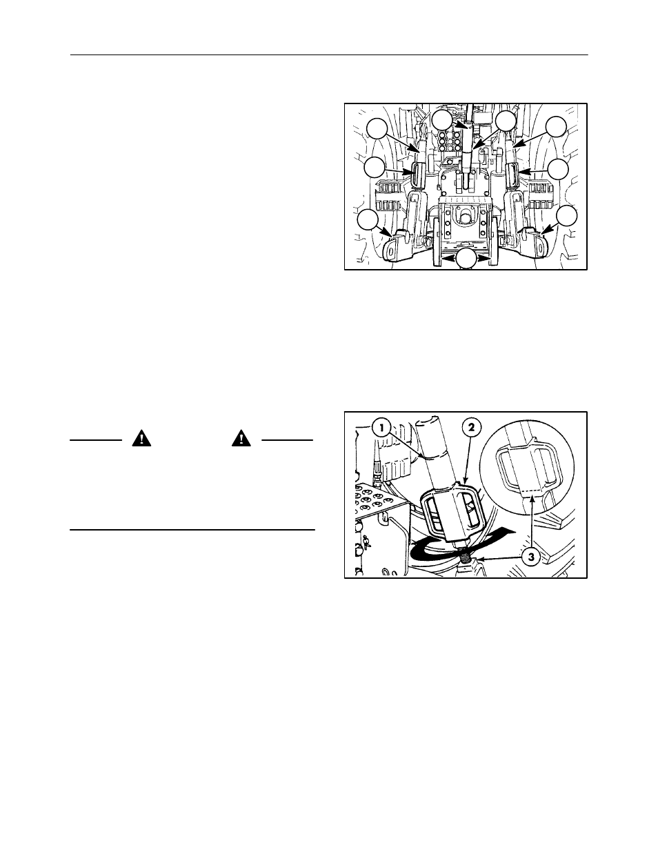
1. Left lift rod
2. Top link
3. Top link transport hanger
4. Right lift rod
5. Right lift rod adjusting block
6. Right lower link
7. Sway blocks
8. Left lower link
9. Left lift rod adjusting block
NOTE: Before attaching equipment read this section
carefully.
When attaching mounted equipment to the three-
point linkage, the following adjustments may be
made to ensure satisfactory operation:
1
2
3
4
5
6
7
8
9
145
LIFT RODS
WARNING
Before disconnecting a lift rod from the lower
link, lower attached equipment to the ground and
make sure the hydraulic control lever is fully
down. Stop the engine. Make sure attached
equipment is correctly supported before remov-
ing the lift rod securing pin.
To adjust either lift rod, 1, raise the adjusting block,
2, and rotate it to lengthen or shorten the lift rod
assembly. To prevent rotation of the adjusting block,
slip it down to engage on the locking boss, 3, on the
lift rod end. For most implements adjust both lift rods
so the centers of the lower link balls are 254 mm (10″)
above the ground when the hitch is fully lowered.
Adjust the lift rods to level the equipment in the
operating position.
146