Buhler 2180 User Manual
Page 78
SECTION 2 - OPERATION
2-32
Setting Implement Width
In order that the modules may calculate the work
done, the working width of the implement in use must
be entered into the memory.
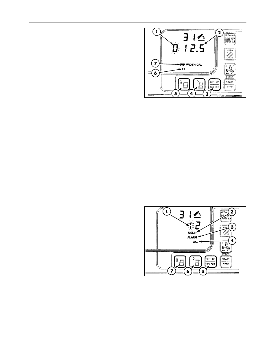
Implement width is a four-digit display and will
appear as “000.0” feet, 2, or “00.00” meters with the
left-hand digit, 1, flashing. “IMP WIDTH CAL,” 7, and
either “FT,” 6, or “METERS” will also be displayed.
Touch the digit select switch, 4, to move the flashing
digit to the right. Touch the digit set switch, 5, to
increase the numerical value of the flashing digit.
For example: To set an implement working width of
12.5 feet, a display of “012.5” is required. Touch the
DIGIT SELECT switch, 4, to cause the second digit
from the left to flash. Touch the DIGIT SET switch, 5,
to change the flashing digit from “O” to “1.”
Use the DIGIT SELECT, 4, and DIGIT SET, 5,
switches to change the remaining digits until “012.5”
is displayed.
NOTE: The area measured will only be accurate if
there is no implement overlap when the tractor turns
around at the end of a run to make another pass.
Alternatively, the implement width entered into
memory may be reduced by the estimated amount of
overlap.
With the required implement width displayed, touch
the SET UP/SELECT switch, 3, to enter the
implement width into memory and change the
display to the % SLIP alarm point.
46
Setting The Slip Alarm Point (Option)
NOTE: If the optional radar unit is not installed, the
slip alarm function will be omitted from the sequence.
The slip alarm point will appear as a two-digit display,
1, with the left-hand digit flashing. “% SLIP,” 2, and
“ALARM,” 3, will also be displayed with the word
CAL, 4.
Use the DIGIT SET, 7, and DIGIT SELECT, 6,
switches to change the value to the required setting.
If the slip alarm is not required, set the display, 1, to
“00.”
With the required slip alarm point displayed, touch
the SET UP/SELECT switch, 5, to change the lower
display to show the first Service Alert Indicator “I.”
NOTE: Slip limit control will not operate below 0.8
km/h (0.5 MPH). Slip limit control will disengage
when the 3-point linkage is raised and re-engage
when the implement is lowered into the ground.
47