Buhler 2180 User Manual
Page 120
SECTION 2 - OPERATION
2-74
ATTACHING EQUIPMENT TO THE PTO
SHAFT
Mount or hitch the equipment to the tractor as
outlined in either “3-Point Hitch Linkage” or “Drawbar
- Towing Attachments” sections.
1. With the engine stopped, all equipment lowered,
and the PTO stopped, unscrew the PTO shaft
cover, 3, Figure 102.
2. Attach the equipment drive shaft to the tractor
PTO shaft. Be certain that the equipment drive
shaft coupler lock pin, 1, engages the PTO shaft
lock groove. If the coupler does not have a lock,
pin the coupler to the shaft.
3. MOUNTED EQUIPMENT ONLY: Raise and
lower the linkage and check for interference.
Make sure the PTO shaft is not binding in the fully
raised position. If necessary, set the height limit
control knob on the right-hand console to limit
raising height. Also study the instructions in
“3-Point Hitch Controls.”
4. TRAILING EQUIPMENT ONLY: Be certain that
the drawbar is fixed in the center position and that
the drawbar is set at the correct length for the
PTO speed selected. See “Drawbar - Towing
Attachments.”
5. Position the PTO master shield, 1, Figure 102, in
the proper position before operating the PTO.
108
6. Check that the PTO driveline is not overex-
tended, bottomed out, or at an excessive angle
and the driveline shield does not contact the PTO
guard or drawbar.
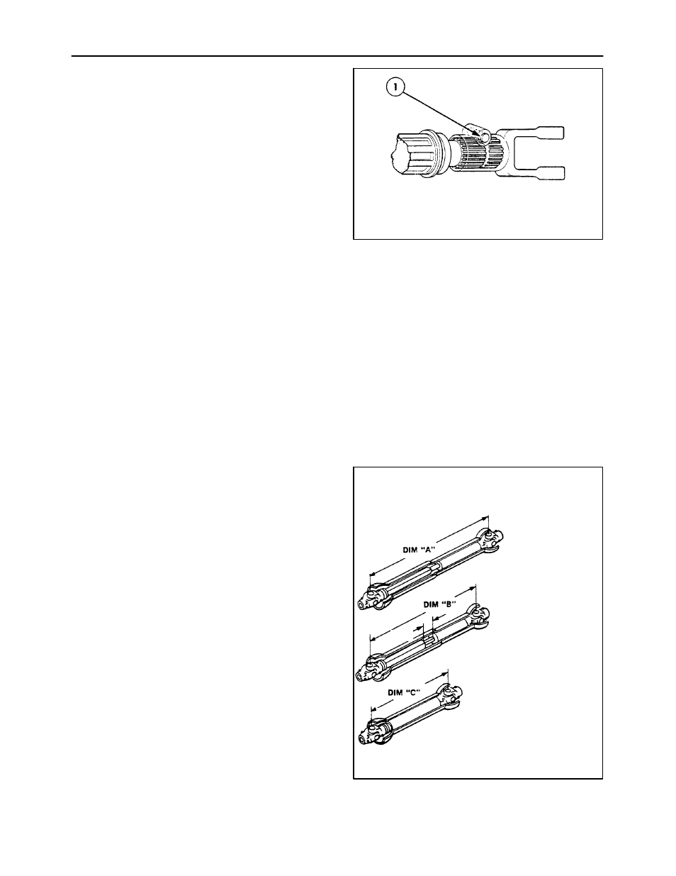
IMPORTANT: Before operating PTO driven equip-
ment, check to make sure the driveline will not bottom
out or become disengaged. Use the following to
determine PTO shaft engagement.
Pull drive halves until fully
extended, just before they
come completely apart. This
is dimension A.
From dimension A, subtract
150 mm (6”) establishing
dimension B.
IMPORTANT: Never operate
equipment with driveline
extended past dimension B.
IMPORTANT: Never operate
equipment with driveline
collapsed past dimension D.
Push drive halves together
as far as possible. This is
dimension C. Add 25 mm (1”)
to dimension C to establish
dimension D.
150 mm
DIM “D” EQUALS
DIM “C” + 25 mm (1”)
(6”)
109