Buhler 2180 User Manual
Page 154
SECTION 2 - OPERATION
2-108
DRAWBAR HEIGHT ADJUSTMENT -
MODEL 2145
This model has a straight drawbar, 1. The drawbar is
not height adjustable but has three length
adjustments.
Distance from
Hitch Point to
Maximum Static
Downward Load
Hole
Hitch Point to
PTO Shaft
kg
lbs
1
355 mm (14″)
2449
5400
2
406 mm (16″)
2086
4600
3
508 mm (20″)
1587
3500
1
162
1. Model 2145 straight drawbar
DRAWBAR HEIGHT ADJUSTMENT -
MODELS 2160, 2180, 2210
These models have a drawbar adjustable for both
height and length. Invert the drawbar to vary the
height of the hitch point above the ground.
IMPORTANT: The clevis and hitch pin retainer must
be moved to the top when the drawbar is inverted.
Distance from
Hitch Point to
Maximum Static
Downward Load
Hole
Hitch Point to
PTO Shaft
kg
lbs
1
406 mm (16″)
2750
6000
2
508 mm (20″)
2131
4700
3
609 mm (24″)
1770
3900
1
2
163
1. Drawbar, low position
2. Drawbar, high position
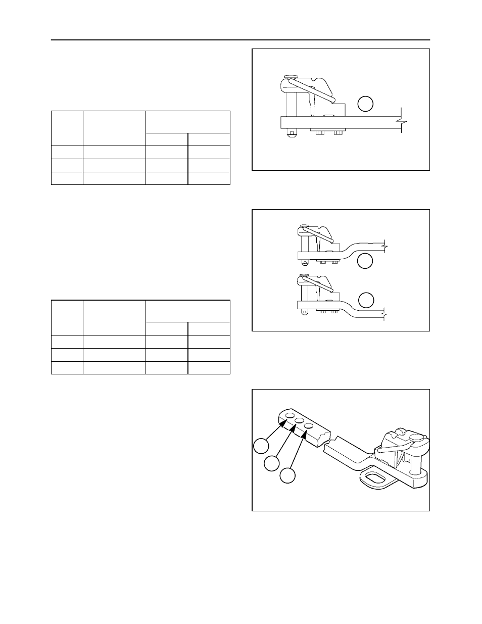
DRAWBAR LENGTH
Three holes, 1, 2, and 3, are provided at the front of
the drawbar for adjusting length. The front locating
pin may be inserted in any of the three holes to vary
the PTO shaft to hitch point distance.
Always use the close-coupled position, 1, for
equipment exerting high downward forces, such as
two-wheeled trailers, etc. The maximum static
downward loads for these models are shown in the
following table. Use the 355 mm (14″) position for
540 PTO equipment, the 406 mm (16″) position for
1000 PTO operation with the 21-spline 35 mm
(1-3/8″) shaft, and the 508 mm (20″) position for 1000
operation with the 20-spline 45 mm (1-3/4″) shaft.
1
2
3
164