Buhler 2180 User Manual
Page 129
SECTION 2 - OPERATION
2-83
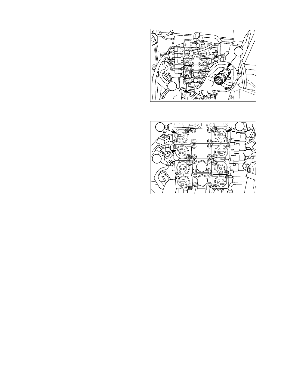
LOW PRESSURE RETURN CIRCUIT
A low pressure return circuit is available by removing
the (1-1/16) - 12 ORB threaded plug, 1, and installing
a low pressure return kit, 2, P/N 86031849. The low
pressure return circuit will reduce back pressure in
the remote hydraulic return line which will result in
more efficient hydraulic motor operation. The return
circuit can also be used in applications where low
return oil pressure is desired to improve implement
operation such as orbit motor case drain lines.
Connect the return line from the hydraulic motor or
implement to the coupler.
NOTE: Connectors and couplers are available from
your authorized dealer.
2
1
123
QUICK COUPLERS
Each control valve has a pair of self-sealing,
leverless quick couplers to facilitate remote cylinder
connection. These couplers also permit remote
cylinder hoses to be pulled from the coupler if an
implement should become disconnected from the
tractor. The left couplers, 1, are identified by an
extended cylinder symbol containing an arrow
pointing in the direction of cylinder travel molded on
the cover. The right couplers, 2, are identified by a
retracted cylinder symbol containing an arrow
pointing in the direction of cylinder travel molded on
the cover. The covers pivot open by pressing on tab
3, to expose the quick coupler.
The covers are color coded (top) gray, brown, blue,
green (bottom) to correspond to the control switches
in the cab console.
The couplers will accept standard (1/2″ )SAE or ISO
tips. The couplers can be connected or disconnected
under pressure. Disconnect pressure is proportional
to system pressure. Increased system pressure will
require increased force to disconnect the couplers.
To connect a remote cylinder hose, open the coupler
dust cover. Clean, then insert the male coupler
making sure the coupler is correctly seated.
Actuate the remote valve to supply hydraulic
pressure which will complete the hydraulic coupling
of the tractor and implement.
To ease removal and installation of the couplers,
relieve the pressure in the system. Securely support
the implement. Make sure no one will be injured by
moving equipment when relieving pressure in the
system. Move the control switch to the float position
with the engine running. This will relieve the
pressure. Turn the engine off with the control switch
still in float. After the engine is shut down return the
control switch to the neutral position. The couplers
can now be connected or disconnected with minimal
pressure and effort.
2
3
1
124