Buhler 2180 User Manual
Page 58
SECTION 2 - OPERATION
2-12
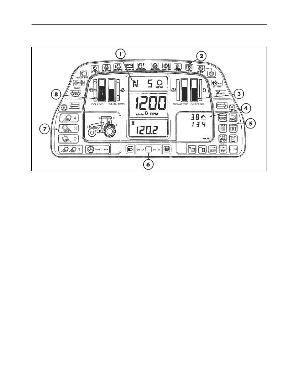
ELECTRONIC INSTRUMENT CLUSTER (EIC)
19
1. Liquid crystal displays (LCD) (3)
2. Indicator lamps (18)
3. Bar graphs (2)
4. Tractor performance monitor (TPM)
5. Touch sensitive programming switches (11)
6. Indicator lamps (3)
7. Touch sensitive light control switches (5)
8. Bar graphs (2)
INTRODUCTION
The electronic instrument cluster (EIC) is shown
above with a normal operating display.
When the key-start switch is turned on, a self-test of
all the Liquid Crystal Display (LCD) segments is
activated, the audible alarm will sound for
approximately one second and all lamps will be
illuminated briefly, to confirm that the bulbs are
functioning. The LCD background areas are
illuminated when the tractor key switch is turned on.
They also have dimmer controlled back lighting.
The EIC is divided into the following areas:
1. The central LCD has transmission gear
information at the top. Engine speed appears in
the middle display and the bottom displays
operating hours, ground speed or PTO speed, as
selected.
2. The upper section consists of colored indicator or
warning lamps, which provide operating informa-
tion or give warning of system malfunctions.
3. Coolant temperature and engine load are
displayed in the right bar graphs.
4. The Tractor Performance Monitor (TPM) is
displayed on the right side of the cluster. The
TPM provides information on 3-point hitch and
other selected system information. Fault code
information is also displayed.
5. Eleven touch-sensitive switches select different
EIC functions for display on the central display
and TPM. The switches are also used for
calibration purposes.
6. The indicator lamps provide operating informa-
tion and give warning of system malfunctions.
7. Five touch-sensitive switches are used to control
the work lights and instrument cluster back-light-
ing brightness.
8. Fuel level and engine oil pressure are displayed
in the left bar graphs.