Buhler 2180 User Manual
Page 172
SECTION 2 - OPERATION
2-126
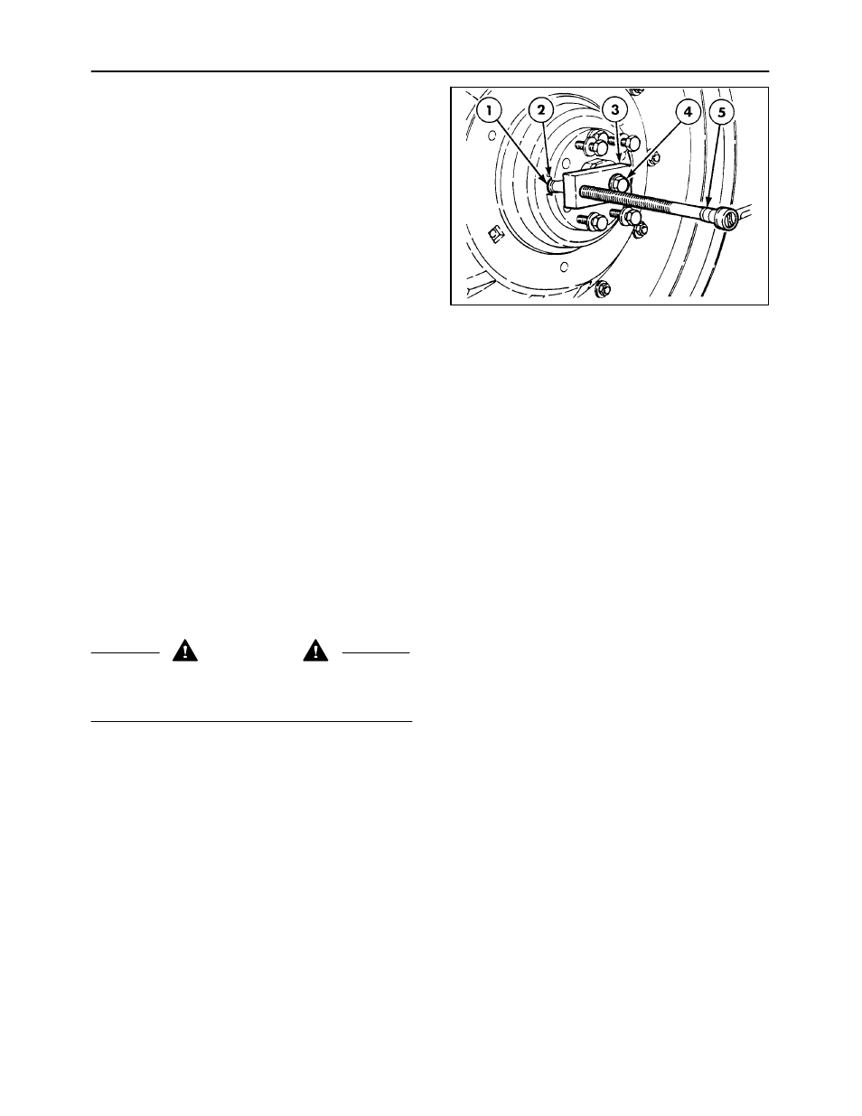
An optional wheel adjustment tool, P/N 9824982, is
available to move the loosened wheel in or out as
required. To use the tool, slide the stepped end, 1,
into the notch, 2, between the wedges. Attach the
block, 3, to the axle with one of the removed wedge
bolts, 4. Turn the adjusting bolt, 5, in or out to move
the wheel assembly.
NOTE: The tool is available through your authorized
dealer.
Set the wheel to the desired position on the shaft.
Remove the pusher bolts and replace them in the
outer holes, 2, Figure 180.
Tighten the six wedge retaining bolts in increments of
68 N·m (50 ft.-lbs.) until a final torque of 391 N·m (290
ft.-lbs.) is achieved.
IMPORTANT: The wedges must be pulled tight
evenly.
Repeat the procedure on the other wheel, making
sure that both rear wheels are the same distance
from the ends of the axle shafts.
NOTE: Check the torque of all six wedge retaining
bolts on each wheel after driving the tractor for 200
m (200 yards), after 1 hour, and 10 hours operation
and thereafter at the 50-hour service intervals.
186
ADJUSTING REAR WHEELS
WARNING
Tractor wheels are very heavy. Handle with care
and make sure, when stored, that they cannot fall
and cause injury.
NOTE: When changing from one track width setting
to another, it may be necessary to interchange the
left- and right-hand wheel assemblies. If so, be sure
that the “V” of the tire tread remains pointing in the
direction of forward travel.
Rear wheel track adjustment is effected by changing
the position of the disc, and/or wheel rim, relative to
the rear axle as shown in Figures 178 and 179.
In each position, a range of track settings may be
achieved by moving the wheel assemblies in or out
on the axle shafts.
To change wheel position, follow all steps outlined in
“Rear Wheel Track Adjustment.”