Buhler 2180 User Manual
Page 124
SECTION 2 - OPERATION
2-78
REMOTE CONTROL VALVES
Remote control valves are available to operate
external hydraulic cylinders, motors, etc. Up to four
remote control valves may be installed. The valves
are located at the rear of the tractor.
Tractors with a standard hydraulic system can be
equipped with three or four remote valves.
HydraFlow Plus tractors will be equipped with four
remote valves.
The bottom control valve, 1, has absolute flow priority
over the remaining valves, 2, 3 and 4.
STANDARD FLOW TRACTORS
After the number I valve has been satisfied, priority
goes to the valve with the lowest resistance.
HYDRAFLOW PLUS TRACTOR
After the number I valve has been satisfied, priority
goes to valve II. The HydraFlow Plus pump supplies
oil to the 3-point hitch valve, valve IV and III, with the
valve having the lowest resistance having priority.
Priority is greatly effected by the setting of the flow
control valves. Make sure the flow controls are
properly adjusted. See “Flow Control Adjustment”
later in this section for more information.
Load checks are installed in the “extend” port of the
lower two control valves I and II.
NOTE: The total system flow is not available to
operate any one single hydraulic circuit. The
maximum available flow from any one remote valve
is 102
±
8 L/min (27 GPM
±
2 GPM)
4
1
2
3
114
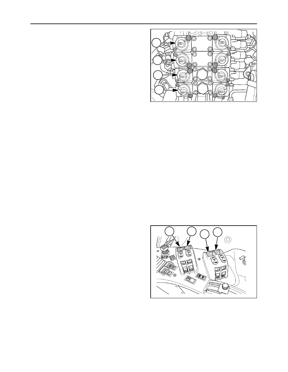
1. Remote valve I (green) with load check
2. Remote valve II (blue) with load check
3. Remote valve III (brown) (if equipped)
4. Remote valve IV (gray) (if equipped)
CONTROL SWITCHES
The electro-hydraulic remote valves are operated by
finger controlled switches in the right-hand console.
Each control switch is colored to correspond to the
color on the remote valve. The numbers in Figure
(113) and (114) match up the control switches,
remote valves and color coding.
1. Control switch I
Green
2. Control switch II
Blue
3. Control switch III
Brown
4. Control switch IV
Gray
1
2
4
3
115