Buhler 2180 User Manual
Page 253
SECTION 3 - LUBRICATION AND MAINTENANCE
3-65
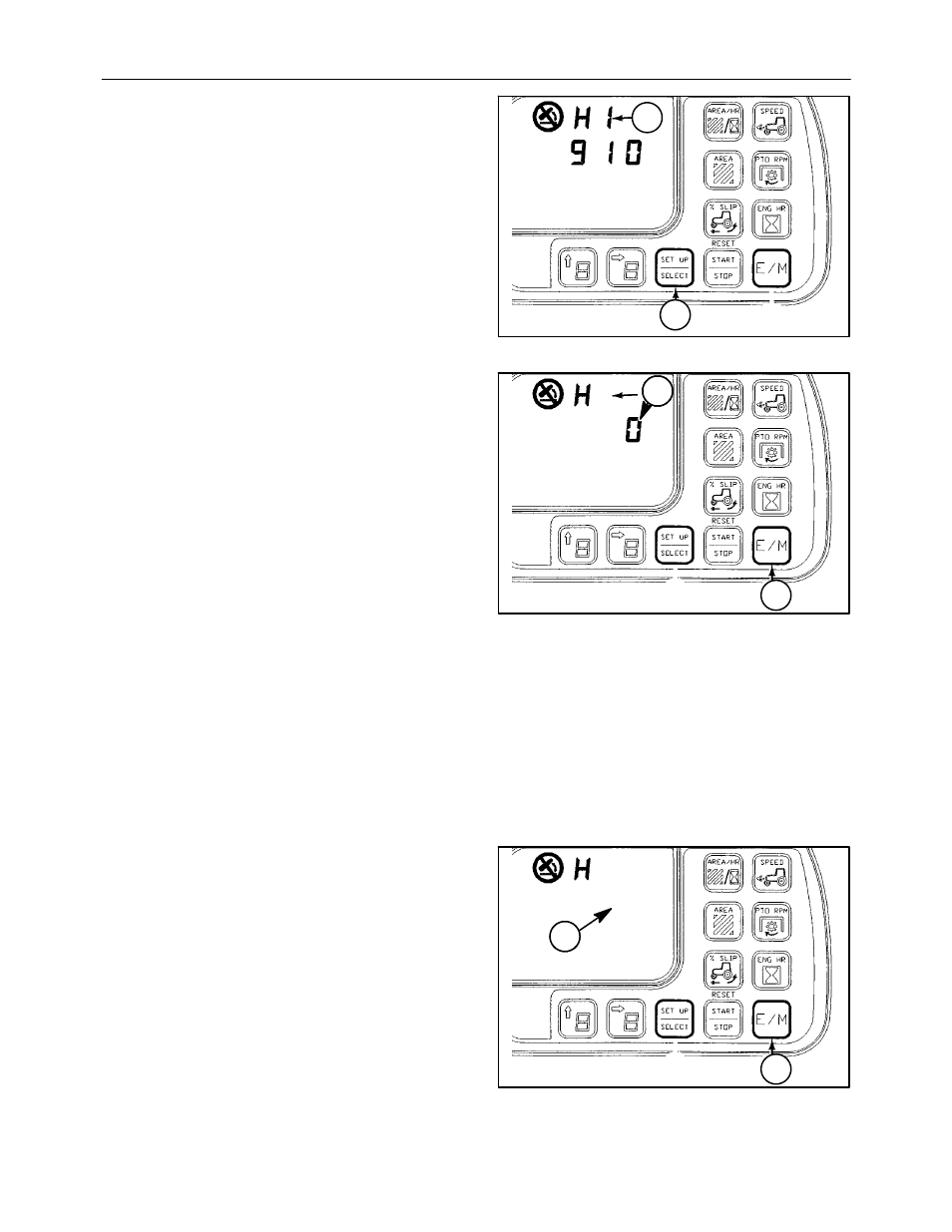
2. When “H1” appears, 1, advance to “H6” using the
SET UP/SELECT switch, 2.
1
2
112
The “H6” calibration status, 1, should be “0”
indicating the system is OK for valve calibration.
NOTE: If “0” does not appear in “H6” the system will
not calibrate. If “H6” indicates any other value exit
mode 11 and repeat the Pre Steps then verify system
status.
3. Exit mode 11 by depressing the E/M switch, 2,
once to display hitch position.
4. Lower the hitch below the 3-point hitch position
display of 60, then raise it above 60 but less than
90. You will observe the hitch moving slightly at
this time. It will cycle up and down about one
position count to find valve raise and lower
thresholds.
NOTE: The hitch will cycle up/down three or more
times until three cycles are verified by the
microcontroller. This will take several minutes.
5. While the hitch is cycling up and down, enter
mode 11 and index to “H6”. The “H6” calibration
status should still be “0” indicating the system is
OK for calibration.
1
2
6
11
113
When three cycles are verified by the microcon-
troller, the status will change from “0” to “9”,1,
showing the system performed 3 calibration
cycles.
6. Exit mode 11 by depressing the E/M switch, 2,
twice and return to “NORMAL” display. Move the
quadrant to full up (“99” will be on the TPM
display). Then move the quadrant to full down
(“0” will be on the TPM display) and there should
be no chrome showing on the lift cylinders.
7. The 3-point hitch calibration is now complete.
2
6
9
11
114