Allied Telesis AT-S29 User Manual
Page 113
AT-S29 Management Software User’s Guide
113
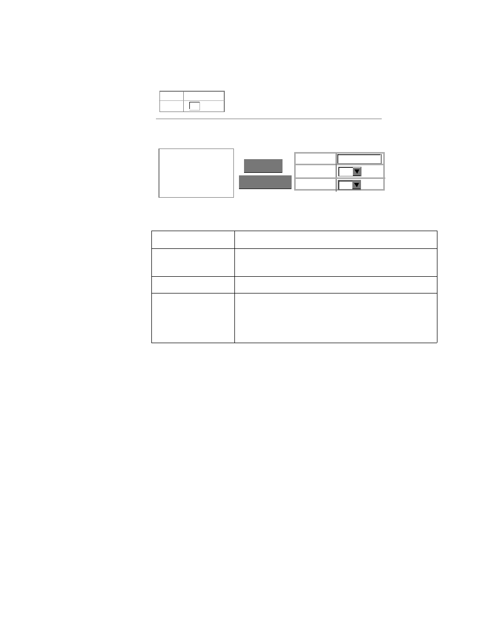
You can use the Port Trunking Configuration screen to set up port trunks
as shown below:
The RJ-45 ports used for each trunk must all be on the same internal
switch chip. The port groups permitted include:
❑
Group 1: 1, 2, 3, 4 and 13, 14, 15, 16
❑
Group 2: 5, 6, 7, 8 and 17, 18, 19, 20
The 100Base-FX fiber optic ports used for one side of a trunk must all be
on the same module. However, the 1000Base-SX and 1000Base-LX ports
used for one side of a trunk may be on any switch in the stack, or both on
the same switch if used as a standalone switch.
For example, when using Gigabit ports to form a trunk within a stack, the
Gigabit ports will all be at Port 25. In this case, you could specify a trunk
group consisting of:
(Unit1-Port25, Unit2-Port25, Unit3-Port25, Unit4-Port25)
or two trunks consisting of:
(Unit1-Port25, Unit2-Port25) and (Unit3-Port25, Unit4-Port25)
Parameter
Description
Trunk
A unique identifier for this trunk. You can
configure up to four trunks per switch.
Status
Enables or disables the displayed port trunk.
Member List
You can create up to 16 trunks for the entire stack
by specifying the trunk identifier, switch unit, and
port number, and then pressing the “Add”
button. Each trunk can contain from 2 to 4 ports.
Trunk 1, Unit 1, Port 1
< Remove Trunk (1-12) Port Unit Trunk 1, Unit 1, Port 2 Current: Member List: 1 1 1 New: Status List: Trunk Status 1 Enable ✓