Output types – AMETEK 1986XPJ Explosion Proof Resolver User Manual
Page 7
7
1080 N. Crooks Road • Clawson, MI 48017 • 800.635.0289 • 248.435.0700 • Fax 248.435.8120 • www.ametekapt.com
AUTOMATION & PROCESS
TECHNOLOGIES
Quadrature Output
A new method of interfacing magnetostrictive
transducers offers an interface as common as
analog with the speed and accuracy of a digital
pulsed type signaling. The Gemco quadrature
LDTs provide quadrature output directly from the
transducer to the controller. The output from the
transducer can be wired directly to any incremental
encoder input or counter card, without the need for
a special converter module or PLC interface card
designed specifically for use with pulsed output
magnetostrictive transducers. The quadrature output
has the “A”, “B” and “Z” outputs. These outputs
are “differential” (also known as balanced), which
means that the connection for each output consists
of two signal wires. These are typically described
as the “plus” and “minus” signals. For example, the
“A” channel consists of “A+” and “A-”. The same
applies to the “B” and “Z” channels. For these
(differential) outputs, the signal is measured with the
reference to the other signal (i.e. the difference or
differential). For example, if the “A+” single voltage
is greater than the “A-” signal, channel “A” is a logic
“0”. Again, this applies to the “B” and “Z” channels
as well. Differential type signals are much less
prone to interference caused by electrical noise
or ground loops more often found in single ended
signal connections. Line drivers are also available
for driving single ended inputs that are not TTL
compatible.
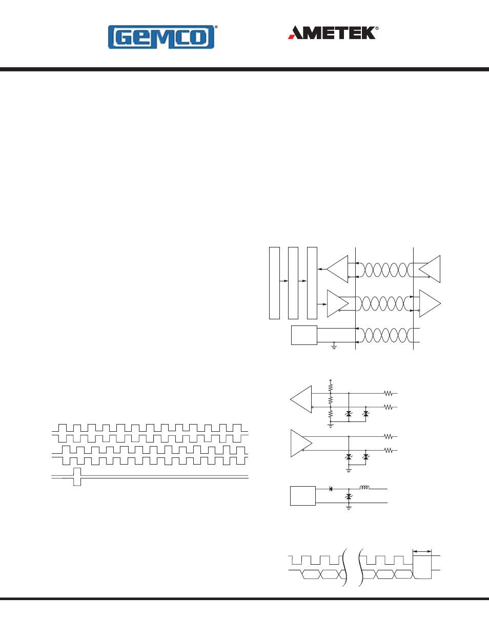
SSI (Synchronous Serial Interface)
Displacement value is encoded into a 24, 25 or
26 Bit format and transmitted at high speeds.
Synchronization in a closed loop system is made
easy. A clock pulse train from a controller is used
to gate out sensor data: one bit of position data is
transmitted to the controller per one clock pulse
received by the sensor. The absolute position data
is continually updated by the sensor and converted
by the shift register into serial information. The
sensors fulfill all requirements to the SSI standard
for absolute encoders.
SSI Clock (+)
SSI Clock (-)
SSI Data (+)
SSI Data (-)
+7 to 30 V
0V
Input
Power
Supply
SSI Shift Register and Controller
Output Data Format Conversion
Position Measurement
SSI Clock (+)
SSI Clock (-)
4.7KΩ
470Ω
4.7KΩ
12V
12V
10Ω
10Ω
SSI Data (+)
SSI Data (-)
12V
12V
10Ω
10Ω
Power Supply (+)
Common
33V
Input
Power
Supply
Ferrite
Filter
+5V
RS-422
RS-422
SSI Logic Diagram
SSI Sensor Input
SSI Timing Diagram
Clock (+)
Data (+)
Clock Interval
LSB
MSB
Min. 16 µs
+A
- A
+B
- B
+Z
- Z
Output Types
- 1986 MD Mill Duty Housing 1986H Servo Mount Resolver 1986GG Multi Turn Dual Resolver 1986G 3 1986F Standard Block Style Resolver 1986E 100mm Face Mount Resolver 1986D 3 1986C 2.06 1986B 2.25 1986A Standard Foot Mount Resolver 956 Blok Housing Option 955S Smart Brik LDT 955LC Brik LDT 955DQ Brik LDT 955D LDT 955C Brik 955A Brik LDT 955 eBrik 953 VMAX LDT 952 BlueOx LDT 950 MD Mill Duty Housing LDT 950IS Intrinsically Safe LDT