Principles of operation – AMETEK 1986XPJ Explosion Proof Resolver User Manual
Page 5
5
1080 N. Crooks Road • Clawson, MI 48017 • 800.635.0289 • 248.435.0700 • Fax 248.435.8120 • www.ametekapt.com
AUTOMATION & PROCESS
TECHNOLOGIES
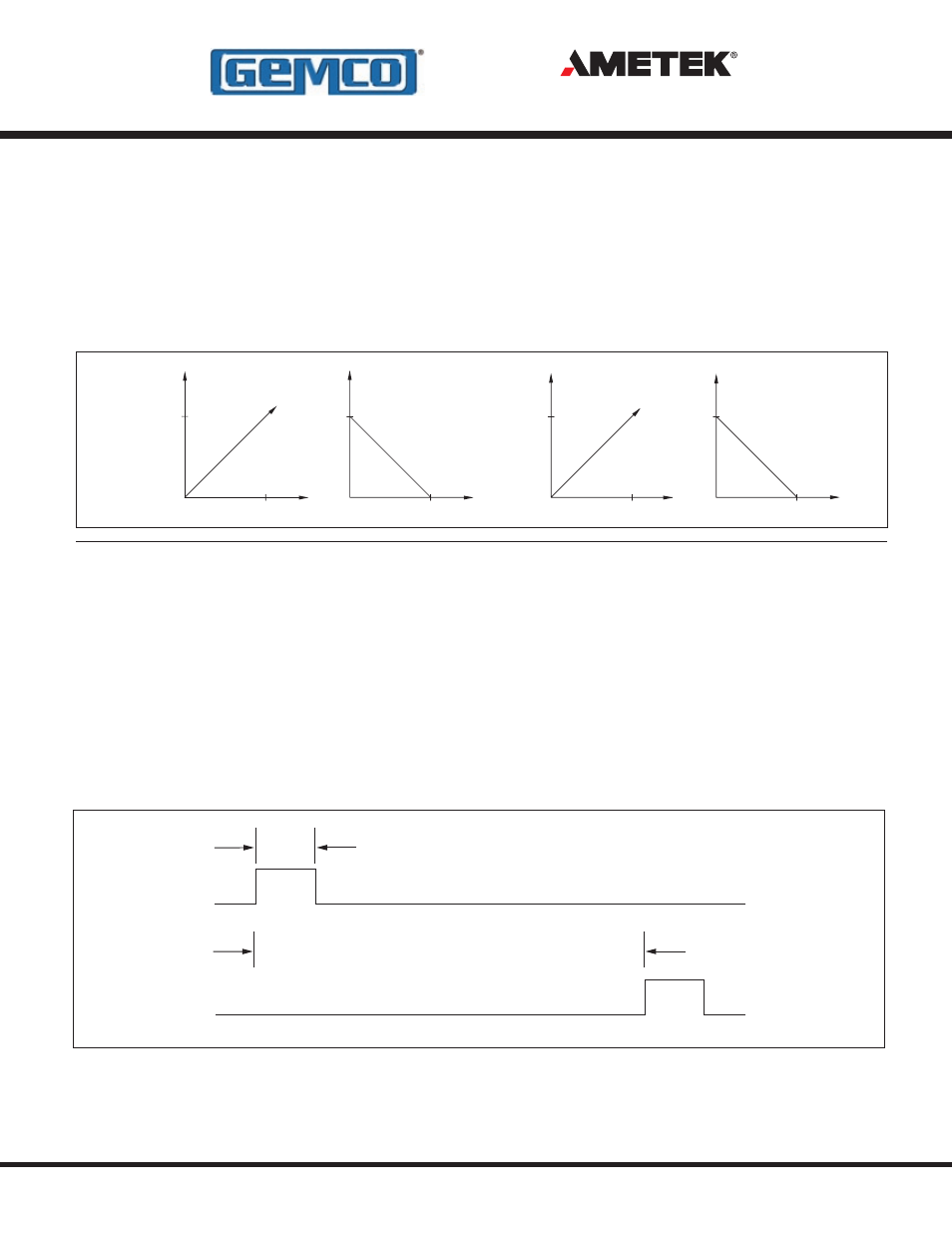
Analog Version
The analog units are an industry standard and
are available with voltage or current outputs. The
output format, voltage or current, is hardware
specified. The 952, 953 and 955 model LDTs
have programmable voltage and current outputs.
The output’s count direction, zero and span are
all programmable. The 952, 953 and 955A and S
units are programmable without any accessories or
adaptors.
1 MICROSECOND (RECOMMENDED)
0.2 MICROSECONDS (MINIMUM)
+ INPUT (START PULSE)
TIME BETWEEN PULSES IS PROPORTIONAL TO
DISTANCE BETWEEN MAGNET AND HEX HEAD
+ OUTPUT (STOP PULSE)
Control Pulse
The control pulse signal interface is a differential
RS422 output. The maximum cable length for the
differential digital LDT is 1,500 feet. To initiate a start
pulse, an external device is used. This start pulse
should be 1.0 microsecond in duration. The time
between the leading edge of the start pulse to the
leading edge of the stop pulse is the proportional
distance from the magnet to the hex head.
10
Full Stroke
Distance
Voltage
Distance
Full Stroke
Voltage
10
4
Distance
Full Stroke
4
Current
20
20
Current
Full Stroke
Distance
Principles Of Operation
- 1986 MD Mill Duty Housing 1986H Servo Mount Resolver 1986GG Multi Turn Dual Resolver 1986G 3 1986F Standard Block Style Resolver 1986E 100mm Face Mount Resolver 1986D 3 1986C 2.06 1986B 2.25 1986A Standard Foot Mount Resolver 956 Blok Housing Option 955S Smart Brik LDT 955LC Brik LDT 955DQ Brik LDT 955D LDT 955C Brik 955A Brik LDT 955 eBrik 953 VMAX LDT 952 BlueOx LDT 950 MD Mill Duty Housing LDT 950IS Intrinsically Safe LDT