955 ebrik, 955e – AMETEK 1986XPJ Explosion Proof Resolver User Manual
Page 36
36
1080 N. Crooks Road • Clawson, MI 48017 • 800.635.0289 • 248.435.0700 • Fax 248.435.8120 • www.ametekapt.com
AUTOMATION & PROCESS
TECHNOLOGIES
955
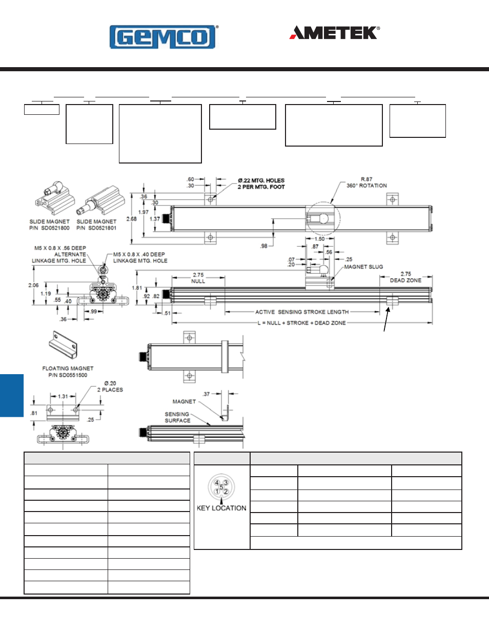
All units are provided with mounting feet
and a magnet assembly. The mounting feet
(SD0522000) slide in the grooves on the side
of the extruded housing. When tightened down
with fastening hardware, the mounting brackets
clamp the unit into place.
955e
955 eBrik™ Output Type
V0 = 0 to 10
V1 = 10 to 0
C2 = 20 to 4mA
C4 = 4 to 20mA
Stroke Length
Insert stroke length to 1 inch
or 25mm. Enter as a four-
place number. Example:
A 12.0” stroke is entered
as 0120 (E) or 100mm is
entered as 0100 (M).
Units of Measure
E = English US inches
M = Metric
Magnet Type
FM = Floating Magnet (Standard)
SM = Slide Magnet Top Swivel
SF = Slide Magnet Front Swivel
X = No Magnet
Options
X = No Options
P = Programmable
Zero & Span
Part Numbering
Dimension Drawing
Accessories
Item
Part Number
Slide Magnet
SD0521800
Slide Magnet Side Adapter SD0521801
Large Float Magnet
SD0551500
Mounting Foot
SD0522000
6 Ft. Cable - Straight
949019L6
12 Ft. Cable - Straight
949019L12
6 Ft. Cable - Right Angle
949020L6
12 Ft. Cable - Right Angle 949020L12
Control Arm
955ARMXX (X = Inches)
Rod Ends
04-570252
Wiring Diagram
PIN Number
Function
Color
1
+VDC POWER SUPPLY
BROWN
2
PROGRAM*
WHITE
3
POWER SUPPLY COMMON
BLUE
4
ANALOG OUT
BLACK
5
ANALOG COMMON
GRAY
*Optional feature must be specified in the part number at time of order.
LDT
Connector
End View
V0
0120
E
FM
X
955 eBRIK
TM
- 1986 MD Mill Duty Housing 1986H Servo Mount Resolver 1986GG Multi Turn Dual Resolver 1986G 3 1986F Standard Block Style Resolver 1986E 100mm Face Mount Resolver 1986D 3 1986C 2.06 1986B 2.25 1986A Standard Foot Mount Resolver 956 Blok Housing Option 955S Smart Brik LDT 955LC Brik LDT 955DQ Brik LDT 955D LDT 955C Brik 955A Brik LDT 955 eBrik 953 VMAX LDT 952 BlueOx LDT 950 MD Mill Duty Housing LDT 950IS Intrinsically Safe LDT