7230 ht digital probe, Part numbering, Dimension drawing – AMETEK 1986XPJ Explosion Proof Resolver User Manual
Page 55
55
1080 N. Crooks Road • Clawson, MI 48017 • 800.635.0289 • 248.435.0700 • Fax 248.435.8120 • www.ametekapt.com
AUTOMATION & PROCESS
TECHNOLOGIES
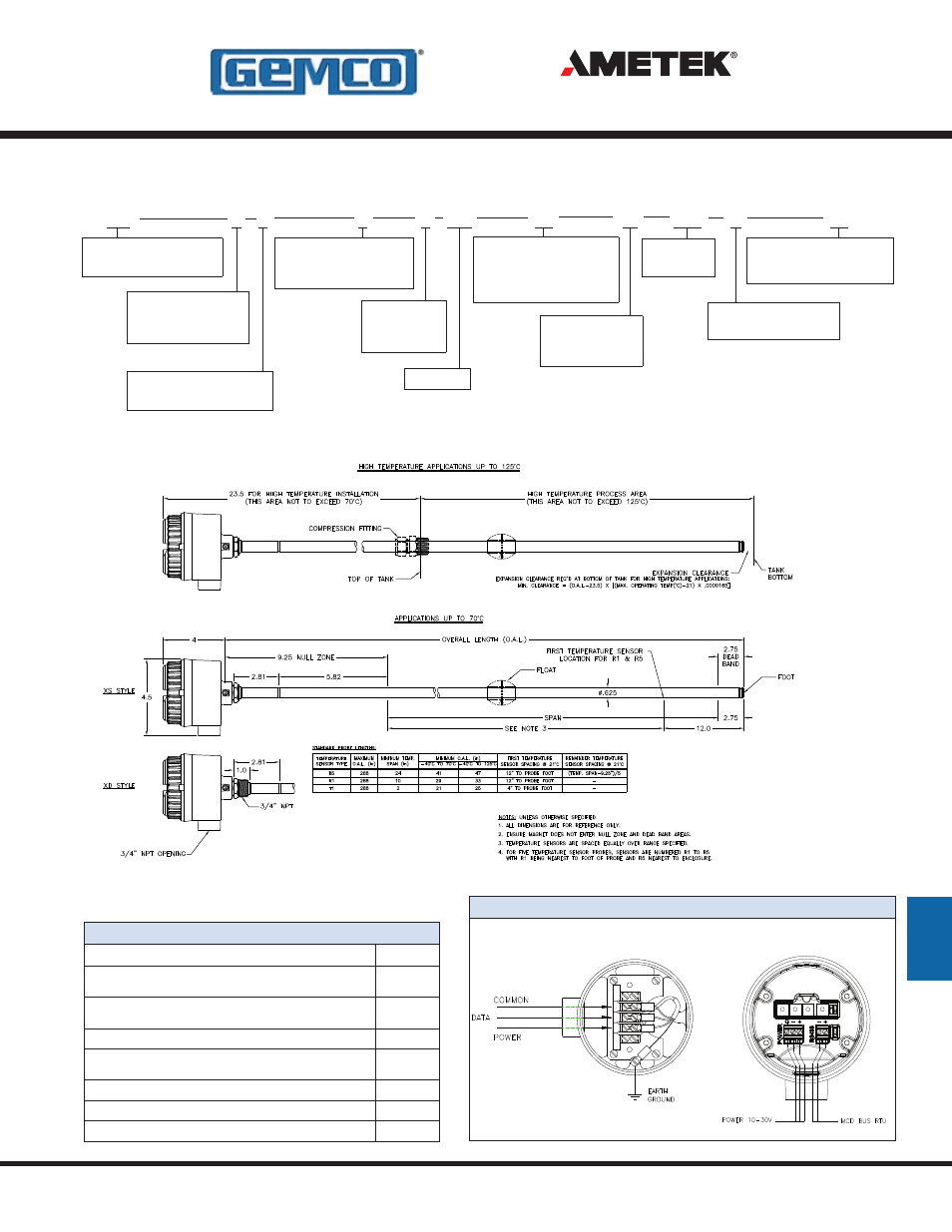
7230
723
X
X
X
X
LLL
Fx
XXX
H
EX
Overall
Length
*
Mounting Style
H
= Condulet
Connector Style
D
= 3/4” NPT Dual
S
= 3/4” NPT Single
Fittings
E
= English
M
= Metric**
7230 Series
HT Digital Probe
Protocol
1
= Modbus
5
= Proprietary ASCII
Span*
# of Floats
F1
= 1 Float
F2
= 2 Floats
Special Mounting
EX
= FM/CSA
Style/Material
X
= 316 Stainless Steel
* Specified in whole 1” increments.
See Dimension Drawing for ranges.
Rx
# of Temp Points
R1
= 1 Sensor
R5
= 5 Sensors
T1
= 1 Sensor
Dimension Drawing
Part Numbering
7230 Wiring Diagram
7235 Wiring
7231 Wiring
Accessories
Item
P/N
Float Kit: Level Float, 316SS, 2.05” dia., 0.54sg Float,
E-clip & spacer
SD0557200
Float Kit: Interface Float, 316SS, 2.05” dia., 0.96sg Float,
E-clip & spacer
SD0556800
Float Kit: Level Float, Nitrophyl 2.0” d x 3.0” h 0.40sg, E-clip & spacer
SD0548600
Float Kit: Interface Float (w/Nitro. level float), 316SS, 2.05” dia.,
0.96sg, E-clip & spacer
SD0557300
Adjustable Tube Coupling: 316SS, 5/8” x 3/4” NPT
04283800
Reducing Bushing: 316SS, 2” x 3/4” NPT
04587241
Analog Interface Board: Modbus RTU to analog (4-20mA) converter
04534047
D
AT
A
PW
R
C
O
M
7230 HT Digital Probe
- 1986 MD Mill Duty Housing 1986H Servo Mount Resolver 1986GG Multi Turn Dual Resolver 1986G 3 1986F Standard Block Style Resolver 1986E 100mm Face Mount Resolver 1986D 3 1986C 2.06 1986B 2.25 1986A Standard Foot Mount Resolver 956 Blok Housing Option 955S Smart Brik LDT 955LC Brik LDT 955DQ Brik LDT 955D LDT 955C Brik 955A Brik LDT 955 eBrik 953 VMAX LDT 952 BlueOx LDT 950 MD Mill Duty Housing LDT 950IS Intrinsically Safe LDT