952a blueox, Part numbering – AMETEK 1986XPJ Explosion Proof Resolver User Manual
Page 20
20
1080 N. Crooks Road • Clawson, MI 48017 • 800.635.0289 • 248.435.0700 • Fax 248.435.8120 • www.ametekapt.com
AUTOMATION & PROCESS
TECHNOLOGIES
952
Note 1: On unsupported stroke lengths greater than 4 feet, rod
support bracket(s) and a special magnet should be used.
Note 2: Specify magnet as separate line item (standard magnet
is SD0400800).
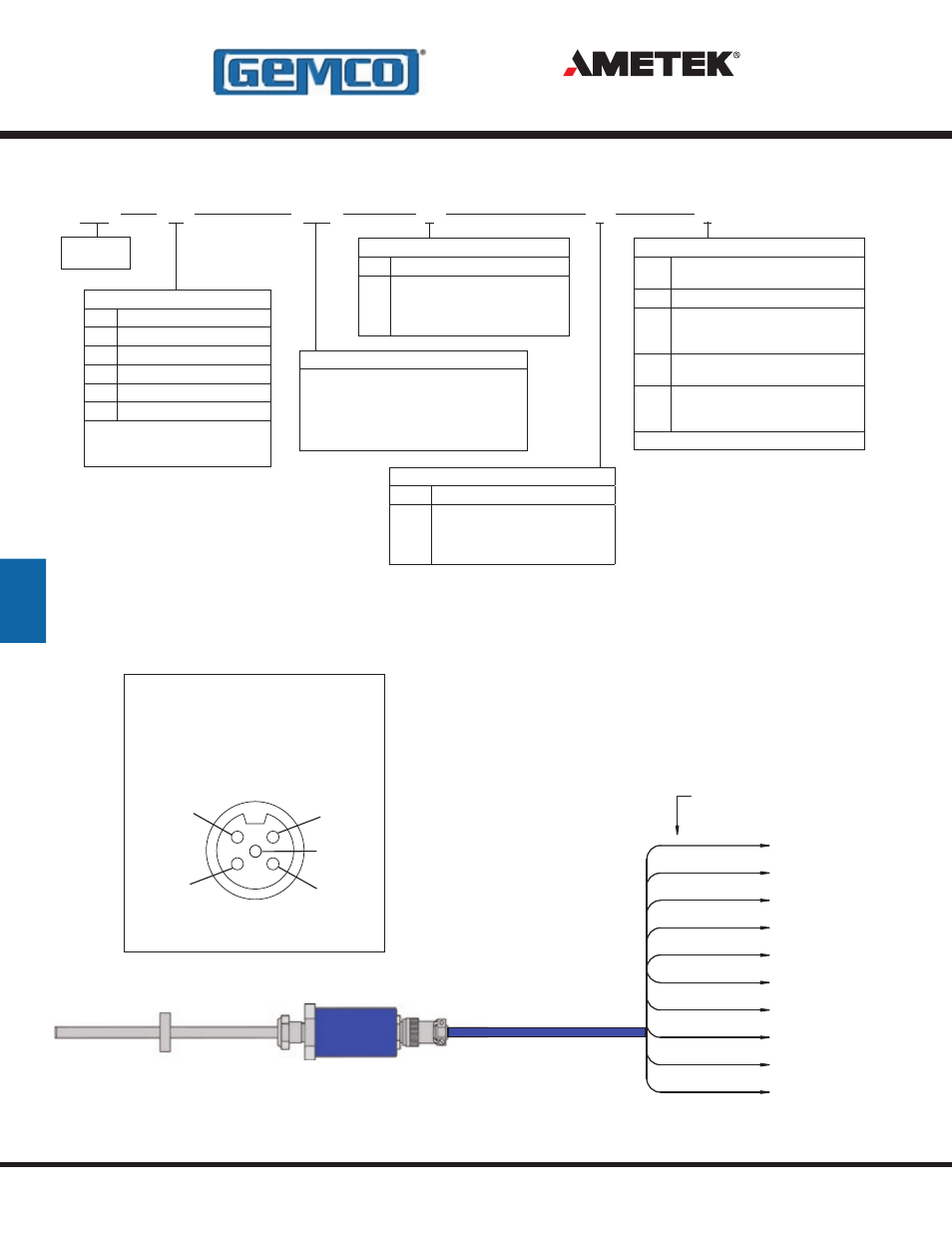
Wiring Diagram Option “E”
LDT Connector View
Use Euro Connector (micro 12 mm single
keyway) cordsets, available from most connector
manufacturers or purchased from Ametek.
3
2
4
1
Power 15 to 30 VDC
(brown wire)
Position
Output
(black wire)
Power Supply Common
(blue wire)
Program Input
(white wire)
5
Position Common
(gray wire)
Wiring Diagram
Option “S”
WHITE
BLUE
BROWN
GRAY
RED
BLACK
PROGRAM INPUT
NO CONNECTION
POSITION OUTPUT
POSITION COMMON
+15/+30 VDC
POWER SUPPLY
ORANGE
NO CONNECTION
PIN-OUT FOR STANDARD
CIRCULAR CONNECTO
AT TRANSDUCER HEAD
GREEN
YELLOW
PURPLE
NO CONNECTION
2nd POSITION COMMON
2nd POWER SUPPLY
COMMON
POWER INPUT
COMMON
PIN-B
PIN-C
PIN-K
PIN-E
PIN-F
PIN-A
PIN-G
PIN-D
PIN-H
PIN-J
Part Numbering
952A
0120
Stroke Length
Insert stroke length to 0.1 inch. Enter as
a four-place number. Example: A 12.0”
stroke enters as 0120. To convert metric
strokes, multiply millimeter value by
0.03937 for inch value.
E
X
X
Null Zone
X
Standard 2 inches.
N_
Insert non-standard Null Zone over
2 inches. (Add non-standard portion
of Null length to stroke length to
calculate list price)
Connector Option
S
Standard 12mm 5 pin Euro connector
( CE Approved )*
E
Environmental MS connector*
C_
Potted pigtail cable assembly, insert
pigtail length in feet. Example: C6 = 6
foot cable.
T
Threaded metal connector
(fits MTS - “RB” on Tempo II
TM
or III)
NC
Non-corrosive Stainless Steel, 12mm
5 Pin Euro Connector and Cover. Use
cable P/N 949013 straight connector.
Consult factory for other connector options.
Dead Band
X
Standard 2.5 inches.
D_
Insert non-standard Dead Band over
2.5 inches. (add non-standard portion
of Dead Band length to stroke length
to calculate list price)
*
If option S or E (environmental connector) is selected, mating
connector and/or cable assembly must be ordered separately.
Analog
BlueOx
V0
Output
V0
0 to 10 VDC
V1
10 to 0 VDC
C4
4 to 20mA
C2
20 to 4mA
D0
Differential 0 to 10 VDC*
D1
Differential 4 to 20mA*
*Analog differential output is the
difference between two magnets,
minimum distance is 2.5”
952A BlueOx
- 1986 MD Mill Duty Housing 1986H Servo Mount Resolver 1986GG Multi Turn Dual Resolver 1986G 3 1986F Standard Block Style Resolver 1986E 100mm Face Mount Resolver 1986D 3 1986C 2.06 1986B 2.25 1986A Standard Foot Mount Resolver 956 Blok Housing Option 955S Smart Brik LDT 955LC Brik LDT 955DQ Brik LDT 955D LDT 955C Brik 955A Brik LDT 955 eBrik 953 VMAX LDT 952 BlueOx LDT 950 MD Mill Duty Housing LDT 950IS Intrinsically Safe LDT