953a/d/ssi vmax – AMETEK 1986XPJ Explosion Proof Resolver User Manual
Page 28
28
1080 N. Crooks Road • Clawson, MI 48017 • 800.635.0289 • 248.435.0700 • Fax 248.435.8120 • www.ametekapt.com
AUTOMATION & PROCESS
TECHNOLOGIES
953
Specifications
953SSI
Connector
Interface
953D
Connector
Interface
953A
Connector
Interface
6 Pin 12mm Euro micro, Standard.
Integral cable ass'y, 7 Pin or 8 Pin DIN - option
6 Pin 12mm Euro micro, Standard.
Integral cable ass'y, 6 Pin or 8 Pin DIN or 10 Pin
MS- Optional
5 Pin 12mm Euro micro, Standard
Integral cable ass'y, 6 Pin or 8 Pin DIN or 10 Pin
MS- Optional
Shock
1000 Gs (lab tested)
IEC 60068-2-27
953SSI Output
953D Output
953A Output
Voltage
Current
953A Current Output
953A Voltage Output
24, 25 or 26 Bit, Binary or Gray Code
(optional parity and error bit),
Position Update
RS = RS422 Start/Stop Pulse
VP = RS422 Variable Pulse (PWM),
Internal/External Interrogation
CP = RS422 Control Pulse
TP = TTL Start/Stop Pulse
0-10 VDC, +/-10 VDC, 0-5 VDC, +/-5 VDC
4-20mA
Max Load Resistance: 500 Ohms
Minimum Load Resistance: 2K Ohm
Output Current: Guaranteed 5mA minimum
Analog Ripple: ≤1 mV maximum
Vibration
30 Gs (lab tested)
IEC 60068-2-6
953SSI Update Time
953D Update Time
953A Update Time
Measuring
Length
300 750 1000 2000 5000mm
Measurements/
sec.
3.7k 3.0k 2.3k 1.2k
0.5k
Controller Dependant
< 2mS Typical
Sensor Housing
and Mounting
Hex
Body length 3.2”, hex base 1 3/4” dia., 3/4”x16x1”
thread. Aluminum housing standard, stainless
steel optional.
Displacement
1” to 300"
Guide Tube Pressure
5,000 psi continuous
(10,000 psi spike)
Dead Band
2.50" (63.5 mm) standard, (2.25” Minimum)
Approvals
CE (EMC)
Null Zone
2.00" (50.8 mm) standard, (1.5” Minimum)
Input Voltage
7 to 30 VDC
Hysteresis
0.001”
Enclosure Rating
IP68, IEC 600529
Current Draw
1 watt typical*, 40mA at 24 VDC typical
Non-linearity
< 0.01% or +/- 0.005”, whichever is greater,
(+/- 0.002 Typical)
953SSI
Resolution
953D
Resolution
953A
Resolution
Internal
Output
English or Metric Units
Metric: 1, 5, 10, 20 micron (5 micron standard)
English: .00005", .0001", .0005", .001"
Consult Factory for Others.
Controller Dependant
0.00006”
16-Bit
953A Zero & Span
Adjustability
Factory set at Null & Dead Band locations
Field re-settable at any location within active stroke
Storage Temperature
-40° to 221° F
(-40° to 105° C)
953D Repeatability
953A Repeatability
953SSI Repeatability
Equal to Resolution of Controller
Equal to Resolution
Equal to Output Resolution
Operating
Temperature
Head
Guide Tube
-40° to 185° F ( -40° to 85° C)
-40° to 221° F (-40° to 105° C)
953SSI Measured
Variables
Single Magnet Displacement, Consult Factory for
Velocity or Differential Operation
Diagnostics
Tri-Color LED beside connector/cable exit,
See 'LED Output Summary Table' on page 31
NOTE: Specifications subject to change and are based on a typical 48” stroke.
*One watt typical at 1ms interrogation time with no recirculations. Faster interrogation times and/or recirculations increase power consumption.
SSI (Synchronous Serial Interface)
Displacement value is encoded into a 24, 25 or 26 Bit
format and transmitted at high speeds. Synchronization
in a closed loop system is made easy. A clock pulse train
from a controller is used to gate out sensor data: one bit
of position data is transmitted to the controller per one
clock pulse received by the sensor. The absolute position
data is continually updated by the sensor and converted
by the shift register into serial information. The sensors
fulfill all requirements to the SSI standard for absolute
encoders.
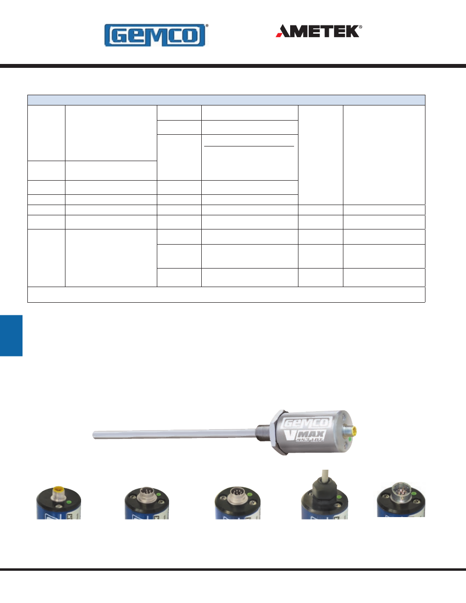
S Connector Style
5 or 6 Pin Micro, 12mm Euro
M Connector Style
6 Pin DIN, Fits MTS D60
7 Pin DIN, Fits MTS D70 (for SSI only)
B Connector Style
8 Pin DIN, Fits Balluff S32
C Connector Style
Integral Cable Assembly
Stainless Steel
Cover and Connector
E Connector Style
10 Pin MS Connector,
Fits Gemco 951 & 952 Wiring
953A/D/SSI VMAX
™
LDT
- 1986 MD Mill Duty Housing 1986H Servo Mount Resolver 1986GG Multi Turn Dual Resolver 1986G 3 1986F Standard Block Style Resolver 1986E 100mm Face Mount Resolver 1986D 3 1986C 2.06 1986B 2.25 1986A Standard Foot Mount Resolver 956 Blok Housing Option 955S Smart Brik LDT 955LC Brik LDT 955DQ Brik LDT 955D LDT 955C Brik 955A Brik LDT 955 eBrik 953 VMAX LDT 952 BlueOx LDT 950 MD Mill Duty Housing LDT 950IS Intrinsically Safe LDT