Alarm reset (rst1, rst2) 33, Alarm standby delay (stb1, stb2) 33, Alarm value (al-1, al-2) 33 – Red Lion TCU User Manual
Page 41
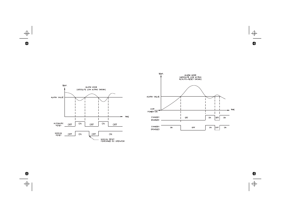
Alarm Reset (rSt1, rSt2)
Each alarm reset action may be independently configured.
LAtC -
Latching
Auto -
Automatic
Latched alarms require operator acknowledgment to reset the alarm
condition. The front panel buttons can be used to reset an alarm when the
controller is in the hidden mode (see
Hidden Function Mode
, page 21). An
Alarm condition may also be reset via the RS485 serial interface or by the user
input. Automatic (Auto) reset alarms are reset by the controller when the
alarm condition clears. Figure 16, Alarm Reset Sequence, depicts the reset
types.
Alarm Standby Delay (Stb1, Stb2)
The alarm(s) may be independently configured to exhibit a power-on,
standby delay which suppresses the alarm output from turning “ON” until the
temperature first stabilizes outside the alarm region. After this condition is
satisfied, the alarm standby delay is canceled and the alarm triggers normally,
until the next controller power-on. Figure 17, Alarm Standby Delay Sequence
depicts a typical operation sequence.
Alarm Value (AL-1, AL-2)
The alarm values are either absolute (absolute alarms) or relative to the
setpoint value (deviation and band alarms). An absolute alarm value is the
value that is entered. A relative alarm value is offset from the temperature
setpoint value by the amount entered and tracks the setpoint value as it is
changed.
AL-1 and AL-2 -
-999 to 9999
If the alarm action is set as a Band Alarm, then only a positive value can be
entered.
AL-1 and AL-2 -
0 to 9999
33
Figure 16, Alarm Reset Sequence
Figure 17, Alarm Standby Sequence