Red Lion GEMINI 33 User Manual
Page 25
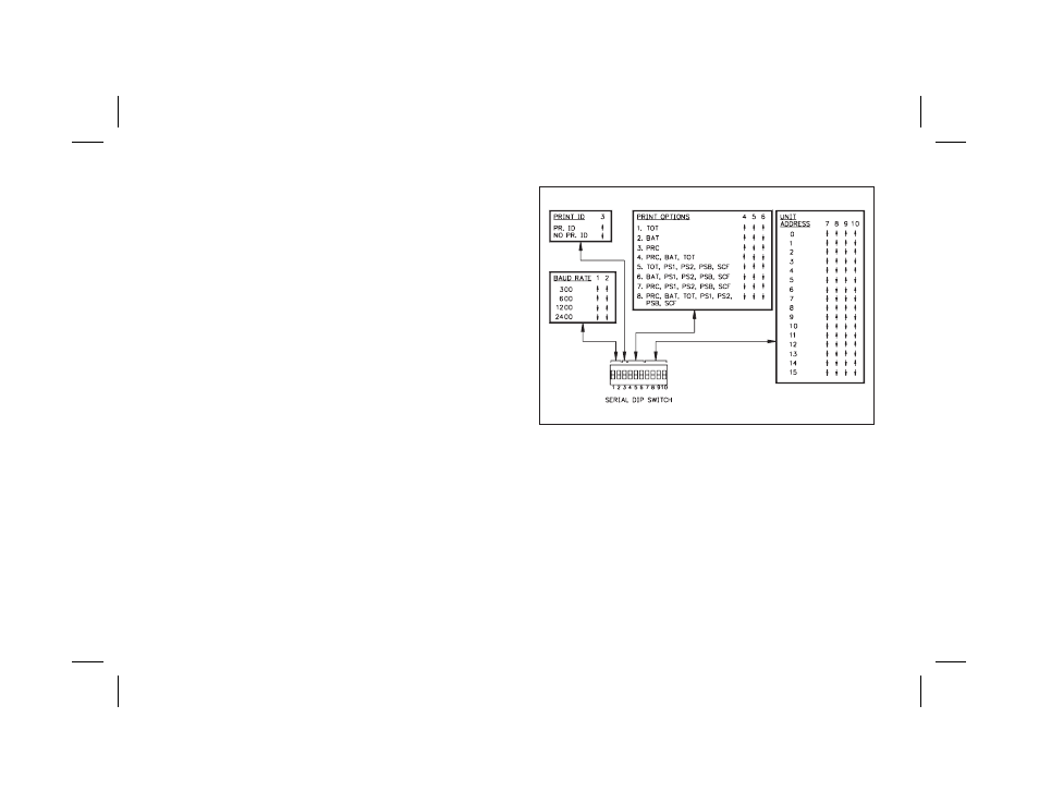
SERIAL DIP SWITCH SET-UP
The Serial DIP switches are accessible through the side of the Gemini 3300. A
list of the DIP switch positions and their functions are shown in Figure 4.
BR0 & BR1, BAUD RATE - Set-up is shown in Figure 4, at right. When
changing the Baud Rate, the unit should be powered-down and then powered
back up again. The unit will only recognize a baud rate change upon
power-up, after activating the “Print Request” terminal or after a few
characters have been sent at the new baud rate (If the two previous conditions
have not occurred, the Gemini will see the characters as erroneous and it will
check the baud rate and set itself to operate at the new rate).
PR.ID - PRINT ID. - When this switch is in the up position, the Gemini 3300
will print the unit address, data value ID and the data value when a
transmission is requested. The unit will also insert a 400 msec delay between
transmissions when the “P” command or Print Request terminal is used. This
switch position is generally used when the unit is connected with a printer.
When the switch is in the down position, the Gemini 3300 will transmit
only the data value, without the unit address and data ID. The 400 msec
delay, described above, will not be inserted. This switch position usage is
intended for applications where the Gemini is communicating with a
computer. In these circumstances printing the address and value ID and
inserting a 400 msec print delay is usually unnecessary and needlessly
slows down communication throughput.
PC0, PC1, & PC2, PRINT OPTIONS - Used to control which values are
transmitted when the Print Request terminal is activated or when the
Transmit per Print Options command “P” is sent to the Gemini 3300.
AD0, AD1, AD2 & AD3, UNIT ADDRESS - These switches are used to give
each unit a separate address when more than one unit is connected in the
Loop. See Figure 4, for Switch Set-up.
-23-
FIG. 4: DIP SWITCH SET-UP