Replacing the controller in its housing, Selection of output 1 type, 4 replacing the controller in its housing – West Control Solutions N6600 User Manual
Page 85: 5 selection of output 1 type
2.4
REPLACING THE CONTROLLER IN ITS HOUSING
To replace the Controller, simply align the CPU PCB and Power Supply PCB with
their guides and connectors in the housing and slowly but firmly push the
Controller into position.
CAUTION: Ensure that the instrument is correctly orientated. A stop will
operate if an attempt is made to insert the instrument in the wrong
orientation (e.g. upside-down). This stop must not be over-ridden.
2.5
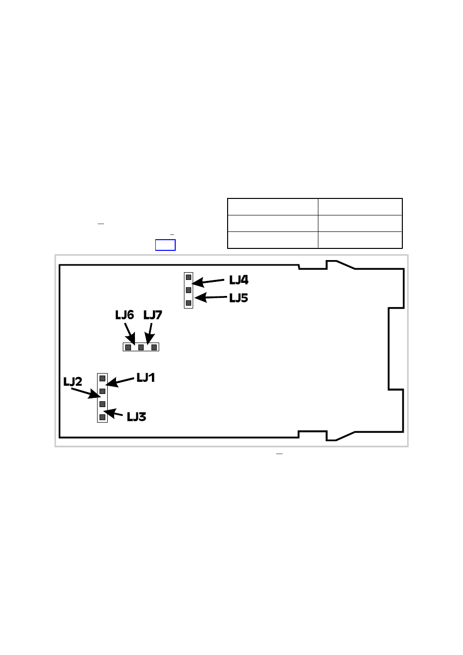
SELECTION OF OUTPUT 1 TYPE
The Output 1 type is selected by Link
Jumpers LJ4, LJ5, LJ6 and LJ7 on the
CPU PCB (
1
16
-DIN Controllers - see
Figure 2-4) or the PSU PCB (
1
8
-DIN
Controllers - see Figure 2-5).
S075-2
2-4
PM-0075
Output 1 Type
Link Jumpers Fitted
Relay or Solid State
LJ5 & LJ6
SSR Drive
LJ4 & LJ7
Figure 2-4
CPU PCB Link Jumpers -
1
16
-DIN Controllers
- 2300 (18 pages)
- 3300 (2 pages)
- 4100+ (177 pages)
- N4100 (79 pages)
- N4400 (38 pages)
- N6500 (2 pages)
- N8800 (88 pages)
- N8840 (90 pages)
- 9300 (2 pages)
- 9500 (24 pages)
- D280-1 (49 pages)
- KS 40-1 (60 pages)
- KS 40-1 Burner (40 pages)
- KS 45 (76 pages)
- KS 50-1 (72 pages)
- KS 90-1 (84 pages)
- KS 90-1 Programmer manual (84 pages)
- KS 94 (44 pages)
- ProVU 4 (184 pages)
- Pro-16 (88 pages)
- Pro-8 (72 pages)
- Pro-4 (84 pages)
- ProEC44 (274 pages)
- CI 45 (60 pages)
- SG 45 (56 pages)
- DataVU 5 (136 pages)
- DataVU 7 (208 pages)
- MRC 5000 Controller Manual (32 pages)
- MRC 5000 Recorder Manual (32 pages)
- MRC 7000 Controller Manual (74 pages)
- MRC 7000 Recorder Manual (64 pages)
- MRC 7000 Profiler Manual (84 pages)
- MRC 8000 (76 pages)
- MRC 9000 (318 pages)
- N8080 (for 1xxx) (40 pages)
- N8080 (for 2xxx) (39 pages)
- TB 40-1 Temperature Limiter (32 pages)
- TB 40-1 Temperature Monitor (32 pages)
- TB 45 Temperature Limiter (51 pages)
- TB 45 Temperature Monitor (52 pages)
- CALogix (44 pages)
- KS 800 Operating Instructions (36 pages)
- KS 800 ISO1745 Interface Manual (34 pages)
- KS 800 Profibus Interface Manual (52 pages)