Controllers fitted with output 1 and output 2, Self-tune, First undershoot - see figure 3-4) – West Control Solutions N6600 User Manual
Page 35
3.4.2 Controllers Fitted with Output 1 and Output 2
Before starting to tune the Controller to the load, check that the Setpoint High and
Low Limits (SPhi and SPLo) are set to safe levels - see Subsections 3.2.12 and
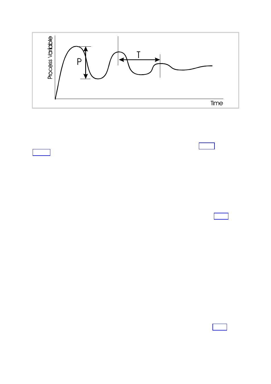
The following simple technique may be used to determine values for proportional
band (Pb1), derivative time constant (rAtE) and integral time constant (rSEt).
NOTE: This technique is suitable for use only with processes which are not
harmed by large fluctuations in the process variable. It provides an
acceptable basis from which to start fine tuning for a wide range of
processes.
1. Tune the Controller using Output 1 only as described in Subsection 3.4.1.
2. Set Pb2 to the same value as Pb1 and monitor the operation of the
Controller in dual output mode. If there is a tendency to oscillate as control
passes into the Output 2 proportional band, increase the value of Pb2. If
the process appears to be over-damped in the region of the Output 2
proportional band, decrease the value of Pb2.
3. When values of proportional bands, integral time constant and derivative
time constant have been determined for tuning, if there is a “kick” as
control passes from one output to the other, set OL to a positive value to
introduce some overlap. Adjust the value of OL by trial and error until
satisfied.
3.5
SELF-TUNE
Once the Controller has been manually tuned, Self-Tune may be used in Operator
Mode to enhance further the response of the Controller (see Subsection 2.15).
O075-3
3-19
PM-0075
Figure 3-4
Manual Tuning Parameters (Output 1 only)