West Control Solutions N6600 User Manual
Page 84
2.2
REMOVING/REPLACING THE OUTPUT 2/OUTPUT 3
OPTION PCBs
With the Controller removed from its housing:
1. Gently push the rear ends of the CPU PCB and Power Supply PCB apart
slightly, until the two tongues on each of the Output 2/Output 3 Option PCBs
become dis-engaged - see Figure 2-2B; The Output 2 Option PCB tongues
engage in holes in the Power Supply PCB and the Output 3 Option PCB
tongues engage in holes on the CPU PCB.
2. Carefully pull the required Option PCB (Output 2 or Output 3) from its
connector (Output 2 Option PCB is connected to the CPU PCB and Output 3
Option PCB is connected to the Power Supply PCB) - see Figure 2-2C. Note
the orientation of the PCB in preparation for its replacement.
Adjustments may now be made to the link jumpers on the CPU PCB, the PSU PCB
and (if fitted) the DC Output 3 Option PCB. The replacement procedure is a simple
reversal of the removal procedure.
2.3
REMOVING/REPLACING THE RS485 OPTION PCB
OR DUAL SETPOINT/REMOTE HEATER CURRENT
TRANSFER OPTION PCB
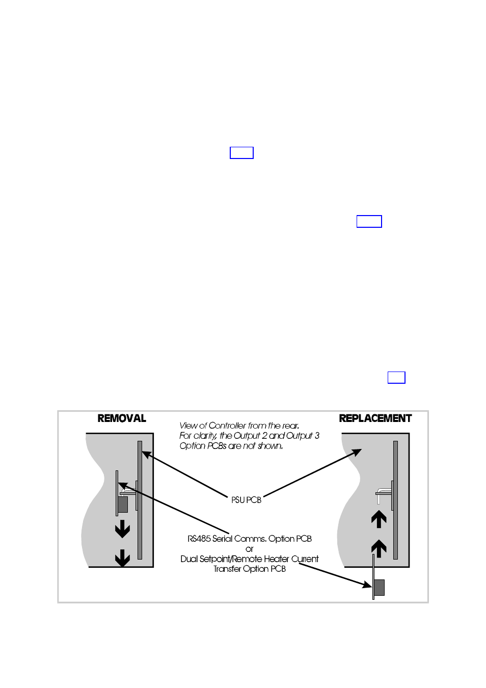
The RS485 Communications Option PCB or Dual Setpoint/Remote Heater Current
Transfer Option PCB is mounted on the inner surface of the PSU PCB and can be
removed when the Controller is removed from its housing (see Subsection 2.1)
Figure 2-3 illustrates the removal/replacement procedure. It is not necessary to
remove the Output 2/Output 3 Option PCBs to perform this procedure.
2-3
S075-2
PM-0075
Figure 2-3
Removing/Replacing the RS485 Communications Option PCB or
Dual Setpoint/Remote Heater Current Transfer Option PCB