KROHNE TIDALFLUX IFM 4110 PF EN User Manual
Page 53
7.30830.32.00
53
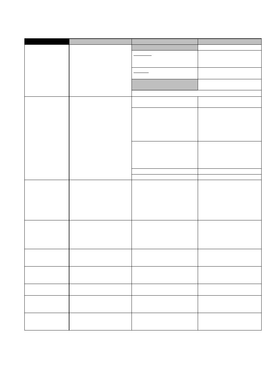
Group I
Faults / Symptoms
Cause
Remedial action
Display shows…
I SHORT
Current output shorted,
load < 15
Ω
Eliminate short circuit,
load must be
≥
15
Ω
!
I OPEN
Load > 500
Ω
Find interruption and eliminate.
No information displayed after
test
I1
Receiver instrument indicates
“0”.
Invoke test function 2.03 for
analysis see Sect. 7.4
as described for faults I2 and I9
Wrong connection / polarity
Connect properly,
see sect. 2.5.2 and 2.5.6.
Defective circuit and/or receiver
instrument
Check circuit and receiver
instrument at I+ / I- and replace
if necessary.
Check fuse F9 on I/O PCB and
replace if necessary, see sect.
8.4 and 8.5.
Defective current output
Replace I/O PCB (see sect.
8.4) or consult Krohne Service,
having first noted down
hardware information and error
status, see sect. 7.3, Fct. 2.02.
Wrong flow direction setting
Set properly in Fct. 3.1.
I2
Receiver instrument indicates
“0”.
Current output switched off
Switch on in Fct. 1.5.
I3
22 mA are available at current
output (fault current)
Range of current output I is
exceeded
Check instrument parameters
and correct if necessary (see
sect. 2.5.2 and 5.7) or consult
Krohne Service, having first
noted down hardware
information and error status, see
sect. 7.3, Fct. 2.02.
I4
22 mA are available at current
output (fault current) and red
LED flashes
Fatal error
Replace signal converter or
consult Krohne Service, having
first noted down hardware
information and error status, see
sect. 7.3, Fct. 2.02.
I5
Unsteady display
Electric conductivity of process
liquid to low
Increase time constant (see
sect. 5.2, Fct.1.2). Also refer to
sect. 6.7.
I6
Receiver instrument indicates
“constant value”
Control input C1 or C2 is set to
“Hold outputs” and is activated
Change setting (see sect. 5.10,
Fct. 1.11 and 1.12), or
deactivate control input.
I7
Jumping current values
Current output is set to automatic
range change
Change hysteresis or tripping
ranges, see sect. 5.19.
I8
F/R mode:
different displays for identical
flow volumes in both directions
Different range set for “forward
flow” and “reverse flow”
Change setting, see sect. 5.15,
Fct. 1.05 “Rev. range”.
I9
Receiver instruments indicates
“min. values”.
Control input C1 or C2 is set to
“Zero outputs” or “Hold outputs”
and is activated
Change setting (see sect. 5.10,
Fct. 1.11 and 1.12) or deactivate
control input.