KROHNE TIDALFLUX IFM 4110 PF EN User Manual
Page 14
7.30830.32.00
14
2.5.3.2 Pulse output A1 for electromechanical totalizers
PLEASE NOTE:
The output terminal A1 can be used as status output A1 or as a 2nd pulse output A1 for electromechanical totalizers.
Setting is as described in Fct. 3.07 HARDWARE.
•
Pulse output A1 is electrically connected to status output A2 (common centre grounding contact A
⊥
) but electrically
isolated from all other circuits.
•
All operating data and functions are adjustable, see Fct.1.07.
•
Active mode:
uses the internal power supply, terminals E+/E-
Passive mode:
requires external power supply, U
ext
≤
32 V DC / 24 V AC, I
≤
100 mA
(I
≤
200 mA for polarized DC operation).
•
Max. adjustable frequency 50 kHz
•
Scaling
in pulses per unit of time (e.g. 10 pulses/s at Q
100%
flow) or
In pulses per unit of volume (e.g. 10 pulses/m
3
or US Gal).
•
Pulse width
symmetric, pulse duty factor 1:1, independent of output frequency,
automatic, with optimum pulse width,
pulse duty factor approx. 1:1 at Q
100%
, or
pulse width range from 0.01 to 1 s adjustable as required for corresponding lower output
frequency.
•
Forward/reverse flow measurement (F/R mode) is possible,
•
Connection diagrams see sect. 2.5.6
•
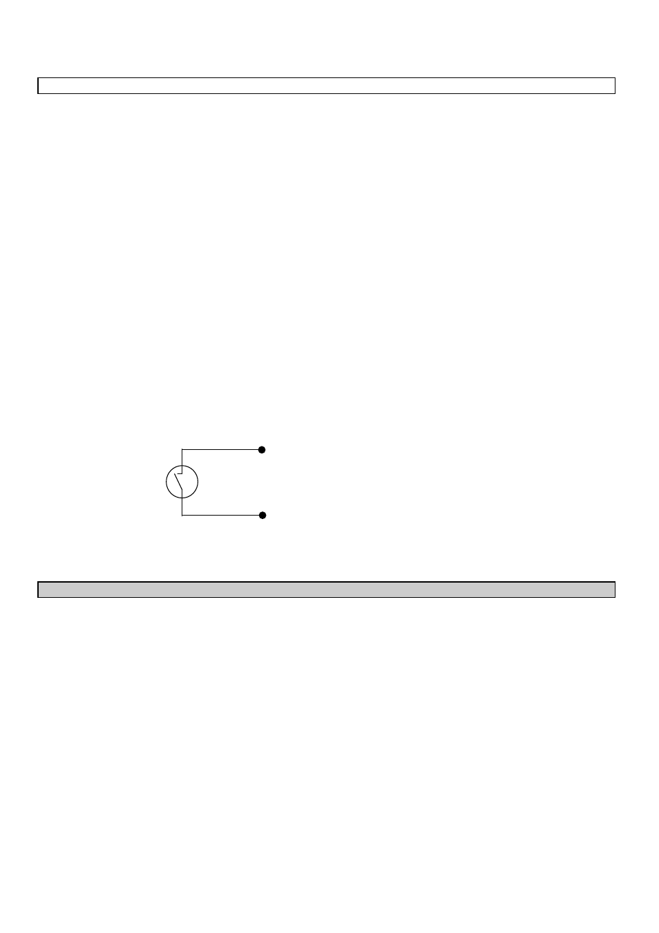
Schematic wiring diagram for pulse output A1 for electromechanical totalizers. This pulse output has a MOSFET switch
as output which switches direct and alternating voltages similar to a relay contact.
2.5.4
Status outputs A1 / A2 / D1 / D2
PLEASE NOTE:
The output terminal A1 can be used as status output A1 or as a 2nd pulse output A1 for electromechanical totalizers.
Setting is as described in Fct. 3.07 HARDWARE.
•
Status outputs A1/A2 and D1/D2 with the common centre grounding contacts A
⊥
and B
⊥
are electrically isolated from
each other and from all other circuits.
•
All operating data and functions are adjustable , see Fct. 1.07-1.10.
•
Active mode:
uses the internal power supply, terminals E+/E-
Passive mode:
requires external power supply, U
ext
≤
32 V DC / 24 V AC, I
≤
100 mA
(I
≤
200 mA for A1 in case of polarized DC operation).
•
The following operating conditions can be signaled using the status outputs:
-
flow direction (F/R mode)
-
limits
-
error messages
-
active range in case of range change-over
-
inverse operation of A1 and A2 or D1 and D2,
i.e. used as change-over switch with common centre grounding contact A
⊥
or D
⊥
.
A1
A
⊥
⊥