KROHNE TIDALFLUX IFM 4110 PF EN User Manual
Page 52
7.30830.32.00
52
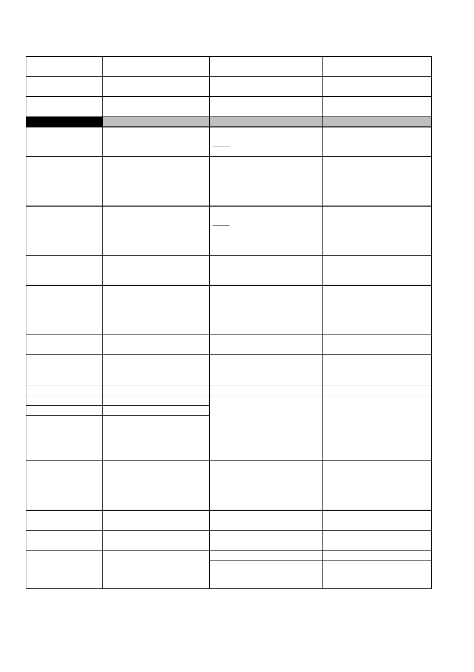
LED 2
Red LED flashes
Fatal error, hardware and/or
software fault
Replace signal converter, see
sect. 8.3
LED 3
Cyclic flashing of red LED,
approx. 1 sec.
Hardware fault
Replace signal converter, see
sect. 8.3
LED 4
Red LED on continuously
Hardware fault
Replace signal converter, see
sect. 8.3
Group D
Display
Cause
Remedial action
D1
LINE INT.
Power failure
Note: no counting during power
failure
Delete error message in
RESET/QUIT. menu, reset
totalizer if necessary.
D2
OVERFL. I
Current output range exceeded
Check instrument parameters
and correct if necessary. Reset
totalizer. Error message is
deleted automatically after
cause has been eliminated.
D3
OVERFL. P
Pulse output range exceeded
Note:
totalizer deviation is possible
Check instrument parameters
and correct if necessary. Reset
totalizer. Error message is
deleted automatically after
cause has been eliminated.
D4
ADW
A/D converter range exceeded
Error message is deleted
automatically after cause has
been eliminated.
D5
FATAL.ERROR
Fatal error, all outputs are set to
“min” values
Replace signal converter, see
sect. 8.3 or consult Krohne
Service, having first noted down
hardware information and error
status, see sect. 7.3, Fct. 2.02.
D6
TOTALIZER
Counts lost
(overflow, data error)
Delete error message in
RESET/QUIT. menu.
D7
I SHORT
Short circuit at current output
Check electrical connection acc.
to Sect. 2.2 and correct if
necessary. Load
≥
15
Ω
!
D8
I OPEN
Open current output
Provide load
≤
500
Ω
!
D9
ADC PARAM.
D10
ADC HARDW.
D11
ADC GAIN
Fault detected on the ADC
printed circuit
Check measuring accuracy.
Replace ADC printed circuit
board (see Sect. 8.4) or consult
Krohne Service, having first
noted down hardware
information and error status, see
Sect. 7.3, Fct. 2.02
D12
STARTUP, cyclic flashing
Hardware fault
Replace signal converter or
consult Krohne Service, having
first noted down hardware
information and error status, see
sect. 7.3, Fct. 2.02
D13
BUSY
Displays for flow, totalizers and
messages disabled
Change setting in Fct. 1.4
D14
unsteady display
Low electrical conductivity,
high solids content, pulsating flow
Increase time constant in Fct.
1.2.
Power supply OFF
Switch on power supply.
D15
No display
Check power supply fuse F7 (F1
and possibly F2 for DC versions)
in terminal compartment
Replace if blown, see sect. 8.1.