KROHNE TIDALFLUX IFM 4110 PF EN User Manual
Page 24
7.30830.32.00
24
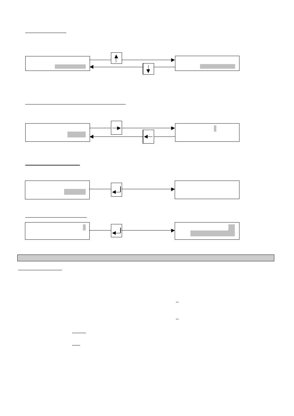
Shift to left
To alter text (units)
In case of units, the numerical
value is converted automatically.
Select next text
Select preceding text
To change from text (unit) to numerical setting
Change to numerical setting
Return to text setting
To change to subfunction
Subfunctions have no “Fct. No.” and are identified by a “
→
” in the upper left corner.
Press key
↵
To revert to function display
Press key
↵
4.4
Table of settable functions
Abbreviations used:
A1, A2 Status outputs
(A1 can also be 2nd pulse output A1)
C1, C2 Control inputs
D1, D2 Status outputs
DN
Meter size, nominal size
F
max
=½ x pulse width (s)
≤
1 kHz if “AUTO” or “SYM.” are selected
in subfunction “PULSWIDTH”
F
min
= 10 pulses/hr
F
M
Conversion factor volume for any unit,
see Fct. 3.05 “FACT. VOL.”
F
T
Conversion factor time for any unit,
see Fct. 3.05 “FACT. TIME”
GK
Primary head constant
I
Current output
I
0%
Current at 0% flow rate
I
100%
Current at 100% flow rate
P (P2) Pulse output (2nd pulse output A1)
P
max
=F
max
/Q
100%
P
min
=F
min
/Q
100%
Q
Current flow rate
Q
100%
100% flow rate = full scale range
Q
max
=
π
4
x DN
2
x v
max
(= max. full-scale range
Q
100%
at v
max
= 12 m/s or 40 ft/s)
Q
min
=
π
4
x DN
2
x v
min
(= min. full-scale range
Q
100%
at v
min
= 0.3 m/s or 40 ft/s)
SMU
Low-flow cutoff for I and P
v
Flow velocity
v
max
Maximum flow velocity (12 m/s or 40 ft/s) at
Q
100%
v
min
Minimum flow velocity (0.3 m/s or 1 ft/s) at Q
100%
F/R
Forward/reverse flow in F/R measuring mode
3 . 7 6 9 9
L i t e r / S e c
9 3 . 3 6 5
U S. G a l / m i n
1 3 . 5 7 1
m 3 / h r
1 3 . 5 7 1
m 3 / h r
2 D I R .
→
→
R A N G E I
1 0 . 3
S E C
F c t . 1. 0 2
T I M E C O N S T .